
Related Manuals for Telex ICW-6


Summary of Contents for Telex ICW-6
- Page 1 ICW-6 Window Intercom Installation and Operation Instructions 93507855000 Rev C 11/2009...
-
Page 2: Proprietary Notice
Proprietary Notice Shipping to the Manufacturer The product information and design All shipments of product should be made via disclosed herein were originated by and are UPS Ground, prepaid (you may request from the property of Bosch Security Systems, Inc. Factory Service a different shipment Bosch reserves all patent, proprietary design, method). -
Page 3: Table Of Contents
Table Contents Introduction ..................3 Unpacking and Inspection ..............3 Recommended Items ................4 Specifications ..................4 Accessories ..................5 Installation and Operation ..............7 Installation ................... 7 Operation ................... 11 Inside and Outside Mic Adjustment Pot ..........11 Mic Adjustment Pot Location ............11... -
Page 5: Introduction
CHAPTER 1 Introduction IMPORTANT: Use the power supply included with the ICW-6. Use of any other power supply could damage the ICW-6 and will void the warranty Unpacking and Inspection ICW-6 Package Cordset - European Cordset - U.S.A. ICW-6 Final Assembly... -
Page 6: Recommended Items
Recommended Items • No.1 Phillips screwdriver • Equipment for cutting/drilling hole(s) for mounting (See Installation section for details) • 1” wide transparent tape • Scissors (For cutting the mounting template from the last page). Specifications General Power Requirement 50mA max @ 110-240VAC, 5VDC 600mA maximum System Frequency Response 200 to 4.5 kHz ±3 dB Environmental... -
Page 7: Accessories
Accessories Description Part Number MCP-90-12 301029000 MCP-90-18 301030000 PH-88-IC3 300852300 PH-44-IC3 300853300 PH-88-IC3-QD 300853301 PH-44-IC3-QD 300853300... -
Page 9: Installation And Operation
CHAPTER 2 Installation and Operation ICW-6 Assembly Detail FIGURE 2. Installation Remove the two (2) screws holding the mounting plate to the operator assembly. (See Figure 2 .) Measure and identify the location where the intercom is to be mounted. - Page 10 Step 1. Screw the threaded end of the ICW-6 power supply interface cord into the ICW- 6. The connector is located on the bottom of the ICW-6 on the operator assembly side. Secure the cord to the glass using wide clear adhesive tape.
- Page 11 Mounting Template FIGURE 4. Customer Side Mounted FIGURE 5.
- Page 12 Connecting customer and operator assemblies prior to final FIGURE 6. mounting.
-
Page 13: Operation
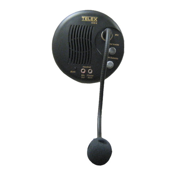
Operation Inside and Outside Mic Adjustment Pot On the ICW-6, you can adjust the sensitivity of the inside and outside mic. This means the how far away from the microphone a person can stand to talk and still be heard. - Page 14 ICW-6 Inside and Outside Mic Pot Location FIGURE 7.
- Page 15 To adjust the inside or outside mic sensitivity level, do the following: Using a small screwdriver, remove the two (2) side screws from the operator side unit. Side Screws Holding the Back Plate to the Operator Unit FIGURE 8. Carefully remove the back plate from the operator side unit. Using Figure 7 , locate the mic pot you want to adjust.
Need help?
Do you have a question about the ICW-6 and is the answer not in the manual?
Questions and answers