Ecco 5500 Series Installation And Operation Instructions Manual
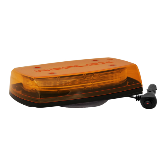
Led microbars
Hide thumbs
Also See for 5500 Series:
- Installation and operation instructions (4 pages) ,
- Installation and operating instructions manual (12 pages) ,
- Assembly, installation and operation instructions (12 pages)
Advertisement
Available languages
Available languages
Quick Links
!
WARNING!
Failure to install or use this product according to manufacturer's recommendations may result in property damage, serious injury, and/or death to
those you are seeking to protect!
Do not install and/or operate this safety product unless you have read and understand the safety information con-
tained in this manual.
1. Proper installation combined with operator training in the use, care, and maintenance of emergency safety devices are essential to ensure the
safety of you and those you are trying to protect.
2. Exercise caution when working with live electrical connections.
3. This product must be properly grounded. Inadequate grounding and/or shorting of electrical connections can cause high current arcing, which
can cause personal injury and/or severe vehicle damage, including fire.
4. Proper placement and installation are vital to the performance of this safety device. Install this product so that output performance of the
system is maximized and the controls are placed within convenient reach of the operator so that s/he can operate the system without losing eye
contact with the roadway.
5. Do not install this product or route any wires in the deployment area of an air bag. Equipment mounted or located in an air bag deployment
area may reduce the effectiveness of the air bag or become a projectile that could cause serious personal injury or death. Refer to the
vehicle owner's manual for the air bag deployment area. It is the responsibility of the user/operator to determine a suitable mounting location
ensuring the safety of all passengers inside the vehicle particularly avoiding areas of potential head impact.
6. It is the responsibility of the vehicle operator to ensure during use that all features of this product work correctly. In use, the vehicle operator
should ensure the projection of the warning signal is not blocked by vehicle components (i.e., open trunks or compartment doors), people,
vehicles, or other obstructions.
7. The use of this or any other safety device does not ensure all drivers can or will observe or react to a warning signal. Never take the right-of-way
for granted. It is your responsibility to be sure you can proceed safely before entering an intersection, driving against traffic, responding at a
high rate of speed, walking on or around traffic lanes.
8. This equipment is intended for use by authorized personnel only. The user is responsible for understanding and obeying all laws regarding
warning signal devices. Therefore, the user should check all applicable city, state, and federal laws and regulations. The manufacturer as-
sumes no liability for any loss resulting from the use of this safety device.
Specifications:
Size:
5545X, 5545XX
5550X, 5550XX
5550XXX
5545X-HBT, 5545XX-HBT
5550X-HBT, 5550XX-HBT
5550XXX-HBT
5545X-VM, 5545XX-VM
5550X-VM, 5550XX-VM
5550XXX-VM
Input Voltage: 12 to 24 VDC systems
Weight:
Mount
Permanent Mount
HBT Mount
Vacuum-Magnet Mount
Installation & Mounting:
Important! This unit is a safety device, and it must be
connected to its own separate, fused power point to assure
its continued operation should any other electrical accessory
fail.
Carefully remove the microbar and place it on a flat surface.
Examine the unit for transit damage, and locate all parts. If dam-
age is found, or parts are missing, contact the transit company or
ECCO. Do not use damaged or broken parts.
Installation and Operation Instructions
11" x 8" x 2.5"
11" x 8" x 3"
5545
5550
approx. 1.9 lbs
approx. 2.0 lbs
approx 2.5 lbs
approx. 4.0 lbs
approx. 3.3 lbs
approx. 3.6 lbs
5500 Series LED Microbars
Current Draw:
5545: 1.48 Amps Max (@ 12VDC Nominal)
18.9 Watts Max (@ 12VDC Nominal)
5550: 4.9 Amps Max (@ 12VDC Nominal)
62.7 Watts Max (@ 12VDC Nominal)
Flash Rate:
See Flash Pattern Chart
Temp. Range:
-22°F to +122°F
-30ºC to +50ºC
Caution: When drilling into any vehicle surface, make sure the area
is free from any electrical wires, fuel lines, vehicle upholstery, etc. that
could be damaged
Permanent Mounting:
1. Select the desired location on a flat surface for the
microbar to be mounted. The visibility of the flash and
ease of wiring access should be taken into
consideration in the selection of the mounting location.
2. Remove lens screws, then remove lens. Use the four holes in the
corners of the base to mark the mounting hole locations.
3. Drill the holes using a 7/32" drill size.
4. A fifth hole may be drilled for wire access.
5. Connect the power wires as shown in the wiring section
(see Figure 6).
6. Mount the microbar with M5 hardware provided.
Page 1 of 6
Advertisement

Related Manuals for Ecco 5500 Series


Summary of Contents for Ecco 5500 Series
- Page 1 Examine the unit for transit damage, and locate all parts. If dam- (see Figure 6). age is found, or parts are missing, contact the transit company or 6. Mount the microbar with M5 hardware provided. ECCO. Do not use damaged or broken parts. Page 1 of 6...
- Page 2 Vacuum-Magnet Mount: The Vacuum-Magnet Mount feature includes a suction cup on the bottom of the microbar, with a magnet inside of the suction cup, for a secure, temporary mount. The microbar should be placed in the WARNING! center of the roof where the least amount of curvature occurs. Before Maximum recommended vehicle speed for safe operation using the installing, make sure the mounting surface is clean and there is no de- Vacuum Mount model is 65 mph (104 km/h), when fitted to the center of a...
-
Page 3: Dimming Feature
FIGURE 2. For more detail about flash patterns, please see the SINGLE and DUAL COLOR FLASH PATTERN TABLES below. 1.5” SYCHRONIZATION: The permanent mount microbars sync with compatible ECCO products via the yellow wire: FIGURE 5 1. Determine the desired style of flash pattern for each unit and set each... - Page 4 DUAL COLOR FLASH PATTERN TABLE TABLA DE PATRONES DE PARPADEO DE COLOR DOBLE TABLEAU DES EFFETS DE CLIGNOTEMENT DE BICOLORE Pa�ern SAE J845 CA T13 ECE R65 5550CXX Red + White Descrip�on Sync Phase White Wire Wire Wire Single - Color 1 Class 1A Class 1A Class 1A Class 1A Class E Class E Class E Single - Color 1 Class 1A Class 1A Class 1A Class 1A Class E Class E Class E...
- Page 5 SINGLE COLOR FLASH PATTERN TABLE TABLA DE PATRONES DE PARPADEO DE COLOR ÚNICO TABLEAU DES EFFETS DE CLIGNOTEMENT DE MONOCHROME SAE J845 CA T13 ECE R65 Pa�ern Descrip�on Sync Phase 5545 5550 Single Class 2A Class 2A Class 1A Class 1A Class 1A Class 1A Class E Class E Class E...
-
Page 6: Customer Service
833 West Diamond St Boise, Idaho 83705 Customer Service USA 800-635-5900 UK +44 (0)113 237 5340 AUS +61 (0)3 63322444 www.eccoesg.com An ECCO SAFETY GROUP™ Brand www.eccosafetygroup.com ©2016 920-0512-00 Rev. H Page 6 of 6... - Page 7 Examine la unidad para detectar si se produjeron daños durante el traslado y ubique todas las piezas. Si se encuentran daños o si faltan piezas, comuníquese con la empresa de transporte o con ECCO. No utilice piezas dañadas o rotas.
- Page 8 Ensamblaje con imanes al vacío: La función del ensamblaje con imanes al vacío incluye una copa de succión en ¡ADVERTENCIA! la parte inferior de la microbarra, con un imán dentro de la copa de succión, para un ensamblaje seguro y temporal. La microbarra debe colocarse en el centro La velocidad máxima sugerida para el vehículo para un uso seguro del del techo en donde ocurre la última cantidad de curvatura.
- Page 9 Las microbarras de ensamblaje permanente se sincronizan con los productos FIGURA 5 ECCO a través del cable amarillo: 1. Determine el estilo deseado de patrón de intermitencia de cada unidad y configúrelas en forma individual (sin conectar los cables amarillo entre si) Cableado: para evitar confusiones.
- Page 10 Limitación de responsabilidad y garantía limitada del fabricante: El fabricante garantiza que al momento de la compra, este producto cumple con las especificaciones del fabricante para el mismo (disponibles a pedido). El fabricante garantiza además que el presente producto está libre de defectos en sus materiales y en su fabricación.
- Page 11 été abîmée dans le transport et repérez toutes les pièces. Si vous repérez un dommage ou des pièces manquantes, contactez la société de transport ou ECCO. N’utilisez pas de pièces cassées ou abîmées. Page 1 sur 4...
- Page 12 Montage à vide magnétique : L’option de montage à vide magnétique inclut des ventouse sur le dessous de la micro-barre, avec un aimant dans la ventouse pour un montage temporaire AVERTISSEMENT! sécurisé. La microbarre doit être placée au centre du toit, à l’endroit où la La vitesse maximale recommandée du véhicule pour une utilisation en courbure est la moins importante.
- Page 13 Mise en synchronisme du mode de clignotement: FIGURE 5 Les modèles à montage définitif 5550 sont synchronisés avec d’autres produits ECCO compatibles par le fil jaune: 1. Déterminez le mode de clignotement souhaité pour chaque unité et réglez Câblage : chaque unité...
- Page 14 état à l’autre. Certains États n’autorisent pas l’exclusion ou la limitation de dommages indirects ou accessoires. 833 West Diamond St Boise, Idaho 83705 Le Service Client États-Unis 800.635.5900 Royaume-Uni +44 (0)113 237 5340 AUS +61 (0)3 63322444 www.eccoesg.com An ECCO SAFETY GROUP™ Brand www.eccosafetygroup.com ©2016 Page 4 sur 4 920-0512-00 Rev. H...
Need help?
Do you have a question about the 5500 Series and is the answer not in the manual?
Questions and answers