HikRobot ID2000 Series User Manual
Industrial code reader
Hide thumbs
Also See for ID2000 Series:
- User manual (125 pages) ,
- User manual (125 pages) ,
- User manual (111 pages)
Table of Contents
Advertisement
Quick Links
Advertisement
Table of Contents

Related Manuals for HikRobot ID2000 Series


Summary of Contents for HikRobot ID2000 Series
- Page 1 ID2000 Series Industrial Code Reader User Manual...
- Page 2 MERCHANTABILITY, SATISFACTORY QUALITY, OR FITNESS FOR A PARTICULAR PURPOSE. THE USE OF THE PRODUCT BY YOU IS AT YOUR OWN RISK. IN NO EVENT WILL HIKROBOT BE LIABLE TO YOU FOR ANY SPECIAL, CONSEQUENTIAL, INCIDENTAL, OR INDIRECT DAMAGES, INCLUDING, AMONG OTHERS, DAMAGES FOR LOSS OF BUSINESS PROFITS, BUSINESS...
- Page 3 EXPLOSIVE OR UNSAFE NUCLEAR FUEL-CYCLE, OR IN SUPPORT OF HUMAN RIGHTS ABUSES. THE PERFORMANCE DATA IN THIS PUBLICATION IS BASED ON HIKROBOT'S INTERNAL RESEARCH/EVALUATION. ACTUAL DATA MAY VARY DEPENDING ON SPECIFIC CONFIGURATIONS AND OPERATING CONDITIONS AND HIKROBOT SHALL NOT BEAR THE CONSEQUENCES ARISING THEREFROM.
- Page 4 ID2000 Series Industrial Code Reader User Manual EU Conformity Statement This product and - if applicable - the supplied accessories too are marked with "CE" and comply therefore with the applicable harmonized European standards listed under the Directive 2014/30/EU(EMCD),Directive 2001/95/EC(GPSD) and Directive 2011/65/EU(RoHS).
- Page 5 ID2000 Series Industrial Code Reader User Manual Available Model This manual is applicable to the ID2000 series industrial code reader. Contact Information Hangzhou Hikrobot Co., Ltd. E-mail: global.support@hikrobotics.com Website: https://en.hikrobotics.com/...
-
Page 6: Table Of Contents
ID2000 Series Industrial Code Reader User Manual Contents Chapter 1 Safety Instruction ................... 1 1.1 Safety Claim ........................1 1.2 Safety Instruction ....................... 1 1.3 Electromagnetic Interference Prevention............... 3 Chapter 2 Overview......................4 2.1 Introduction ......................... 4 2.2 Key Feature .......................... 4 Chapter 3 Appearance .................... - Page 7 ID2000 Series Industrial Code Reader User Manual Chapter 7 Device Connection ..................40 7.1 Install Client Software ....................40 7.2 Set PC Environment ......................41 7.2.1 Turn off Firewall for Network Device ..............41 7.2.2 Set PC Network for Network Device ..............41 7.2.3 Check USB Drive for USB Device...............
- Page 8 ID2000 Series Industrial Code Reader User Manual 9.6.4 Stop Trigger ......................78 9.7 Signal Output Settings ....................82 9.7.1 Select Output Signal .................... 82 9.7.2 Enable Line Inverter ..................... 82 9.7.3 Set Event Source ....................83 9.7.4 Set Buzzer ......................85 9.8 Communication Settings....................
- Page 9 ID2000 Series Industrial Code Reader User Manual 10.4 Set Setting Codes of Code Color ................111 10.5 Set Setting Codes of Code Reading Quantity ............112 10.6 Set Setting Codes of Data Processing..............114 10.7 Set Setting Codes of Aiming System ............... 116 10.8 Set Setting Codes of Light Source ................
-
Page 10: Chapter 1 Safety Instruction
ID2000 Series Industrial Code Reader User Manual Chapter 1 Safety Instruction The safety instructions are intended to ensure that the user can use the device correctly to avoid danger or property loss. Read and follow these safety instructions before installing, operating and maintaining the device. - Page 11 ID2000 Series Industrial Code Reader User Manual meet the Limited Power Source (LPS) requirements. For specific requirements, please refer to the device's technical specifications. ● It is strictly forbidden to wire, maintain, and disassemble the device is powered on. Otherwise, there is a danger of electric shock.
-
Page 12: Electromagnetic Interference Prevention
ID2000 Series Industrial Code Reader User Manual ○ The ability to comprehend the contents of this manual. ● Do not contact the device with strong acids, alkalis, oils, greases or organic solutions such as thinners. ● Do not expose the device directly to flashlights, high-frequency switch lighting devices, or to sunlight, which may affect the performance. -
Page 13: Chapter 2 Overview
Chapter 2 Overview 2.1 Introduction With functions of image acquisition, code recognition and output, the ID2000 series industrial code reader can read different types of 1D codes and 2D codes. It adopts compact design and is small in size. The device is applicable to consumer electronics, food and medicine, automobile spare parts, electronics semiconductor, and other industries. -
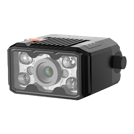
Page 14: Chapter 3 Appearance
ID2000 Series Industrial Code Reader User Manual Chapter 3 Appearance Note Appearance here is for reference only. Refer to the device's specification for detailed dimension information. Refer to the table and figures below for the information and appearance of different device models. - Page 15 ID2000 Series Industrial Code Reader User Manual Figure 3-1 Appearance (Type I) Figure 3-2 Appearance (Type II)
- Page 16 ID2000 Series Industrial Code Reader User Manual Figure 3-3 Appearance (Type III) Figure 3-4 Appearance (Type IV)
- Page 17 ID2000 Series Industrial Code Reader User Manual Figure 3-5 Appearance (Type V) Figure 3-6 Appearance (Type VI)
- Page 18 ID2000 Series Industrial Code Reader User Manual Figure 3-7 Appearance (Type VII) Table 3-1 Component Description Name Description Focus Knob It is used to adjust focal length manually. Screw Hole It is used to fix the device to the installation position.
- Page 19 ID2000 Series Industrial Code Reader User Manual Name Description ● It is in green color lasting 0.5 s when the device reads codes successfully, is solid green when the device reads codes continuously, and is in red color when the device does not read codes.
-
Page 20: Chapter 4 Connector And Cable
ID2000 Series Industrial Code Reader User Manual Chapter 4 Connector and Cable This section introduces the device’s connector, including fast Ethernet interface, USB interface and RS-232 interface, and the supplied cable in the package. Note The device’s connector and connector pin definitions may differ by device models. - Page 21 ID2000 Series Industrial Code Reader User Manual Signal I/O Signal Source Description Supplied Cable Fast Ethernet signal RJ45 Ethernet MDI0+ MDI0+ connector Fast Ethernet signal RJ45 Ethernet MDI1- MDI1- connector It can be configured as GPIO2 Line 2+ input or output, and is Blue/white open line output by default.
- Page 22 ID2000 Series Industrial Code Reader User Manual Signal I/O Signal Source Description Supplied Cable RS232RX RS-232 serial port input DB9 female serial port Fast Ethernet signal RJ45 Ethernet MDI0+ MDI0+ connector Fast Ethernet signal RJ45 Ethernet MDI1- MDI1- connector LineOut 0 signal...
- Page 23 ID2000 Series Industrial Code Reader User Manual Figure 4-2 17-Pin Cable for Type II and Type V Devices Note ● For type II device, the pink line in the open line is Line 0/1’s pull-up and pull-down resistor, and black/white line in the open line is Line 2/3’s pull-up and pull-down resistor.
- Page 24 ID2000 Series Industrial Code Reader User Manual Signal I/O Signal Source Description Supplied Cable Reserved Brown open line Reserved DB9 female serial RS232_TX RS-232 serial port output port DB9 female serial RS232_RX RS-232 serial port input port RJ45 Ethernet MDI0+...
- Page 25 ID2000 Series Industrial Code Reader User Manual Figure 4-4 17-Pin Cable for Type III, Type I and Type IV Devices Note Regarding the cable, black/white line in the open line is Line 0’s pull-up and pull-down resistor, pink line is Line 1’s pull-up and pull-down resistor, orange line is Line 2’s pull-up and pull-down resistor, and purple/white line is Line 3’s pull-up and pull-down resistor.
- Page 26 ID2000 Series Industrial Code Reader User Manual Signal I/O Signal Source Description Supplied Cable OPTO_IN0 LineIn 0+ Non-isolated input 0 6-pin terminal RJ45 Ethernet Fast Ethernet signal TX+ connector RJ45 Ethernet Fast Ethernet signal RX- connector OPTO_OUT LineOut 2+ Non-isolated output 2...
- Page 27 ID2000 Series Industrial Code Reader User Manual Refer to the figure and table below for the pin definitions of the 6-pin terminal. Figure 4-7 6-Pin Terminal Table 4-5 Pin Definitions (6-Pin Terminal) Signal Description Cable Color LINEIN 0 Non-isolated Input 0...
-
Page 28: Device With Usb Interface
ID2000 Series Industrial Code Reader User Manual 4.2 Device with USB Interface Device with USB interface includes type I device to type VII device. Type I to Type V Devices Type I, type II, type III, type IV and type V devices all have a 17-pin M12 connector. Refer to the figure and table below for connector pin definitions. - Page 29 ID2000 Series Industrial Code Reader User Manual Type VI Device Type VI device has a DB15 connector. Refer to the figure and table below for connector pin definitions. Figure 4-10 DB15 Connector Table 4-7 Pin Definitions (Type VI Device) Signal...
-
Page 30: Device With Rs-232 Interface
ID2000 Series Industrial Code Reader User Manual The supplied cable also has four open lines with different colors, and you can wire them according to actual demands. Table 4-8 Open Line Definitions Signal I/O Signal Source Description Color OPTO_OUT0 LineOut 3... - Page 31 ID2000 Series Industrial Code Reader User Manual Caution You cannot use DB9 serial port and VCC to power the device at the same time. Otherwise, damaging to power supply may occur.
-
Page 32: Chapter 5 Installation
ID2000 Series Industrial Code Reader User Manual Chapter 5 Installation 5.1 Installation Preparation You need to prepare following accessories before installation. Table 5-1 Accessories Name Quantity Description It refers to the supplied cable that is included in the Cable package. Refer to section Connector and Cable for details. - Page 33 ID2000 Series Industrial Code Reader User Manual ○ The industrial switching power supply has exposed high-voltage terminals, please install it in a closed chassis or cabinet to prevent accidental contact with personnel. ○ The internal components of the power supply should maintain sufficient insulation distance between the mounting screws.
-
Page 34: Chapter 6 I/O Electrical Feature And Wiring
ID2000 Series Industrial Code Reader User Manual Chapter 6 I/O Electrical Feature and Wiring 6.1 I/O Electrical Feature and Wiring of Type V Device 6.1.1 Opto-isolated Input Circuit Type V device's LineIn 0/1 are opto-isolated inputs, and internal circuit is as follows. -
Page 35: Opto-Isolated Output Circuit
ID2000 Series Industrial Code Reader User Manual Table 6-1 Input Electrical Feature Parameter Name Symbol Value Input Logic Level Low 1.5 VDC Input Logic Level High 2 VDC Input Falling Delay 81.6 μs Input Rising Delay 7 μs 6.1.2 Opto-isolated Output Circuit Type V device's LineOut 0/1 are opto-isolated outputs, and internal circuit is as follows. -
Page 36: Input Signal Wiring
ID2000 Series Industrial Code Reader User Manual Table 6-2 Output Electrical Feature Parameter Name Symbol Value Output Logic Level Low 730 mV Output Logic Level High 3.2 VDC Output Falling Delay 6.3 μs Output Rising Delay 68 μs Output Falling Time 3 μs... -
Page 37: Output Signal Wiring
ID2000 Series Industrial Code Reader User Manual DB9 Connector Internal Resistor NPN Device Power ● of Cable Opto-isolated NPN Device Signal Line Input Input Signal Ground NPN Power Ground GND of PWR GND of VCC Figure 6-6 Input Signal Connecting to NPN Device (Pull-Up Resistor of 17-Pin Cable Used) If the VCC of NPN device is 12 VDC or 24 VDC and the external pull-up resistor is used, it is recommended to use 1 KΩ... -
Page 38: I/O Electrical Feature And Wiring Of Other Devices
ID2000 Series Industrial Code Reader User Manual NPN Device If the VCC of NPN device is 12 VDC or 24 VDC, and the pull-up resistor of the supplied 17- pin cable is used. DB9 Connector Internal Resistor NPN Device Power ●... -
Page 39: Non-Isolated Input Circuit
ID2000 Series Industrial Code Reader User Manual 6.2.1 Non-isolated Input Circuit The internal circuit of other devices’ non-isolated input signal is as follows. Figure 6-11 Internal Circuit of Input Signal Input Level High Input Level Low Internal Logic Figure 6-12 Input Logic Level... -
Page 40: Non-Isolated Output Circuit
ID2000 Series Industrial Code Reader User Manual 6.2.2 Non-isolated Output Circuit The internal circuit of the device’s non-isolated output signal is as follows. Figure 6-13 Internal Circuit of Output Signal Internal Logic Output Level High Output Level Low Figure 6-14 Output Logic Level When the external voltage is 12 VDC and pull-up resistor is 1 KΩ, output electric feature is... -
Page 41: Bi-Directional I/O Circuit
ID2000 Series Industrial Code Reader User Manual External Voltage Output Logic Level Low (VL) 12 VDC 500 mV 24 VDC 900 mV 6.2.3 Bi-directional I/O Circuit The bi-directional signal in I/O signal can be use as input signal or output signal according to demands. -
Page 42: Input Signal Wiring
ID2000 Series Industrial Code Reader User Manual Configured as Output Signal Internal Logic Output Level High Output Level Low Figure 6-17 Output Logic Level When the external voltage is 12 VDC and pull-up resistor is 1 KΩ, output electric feature is shown below. - Page 43 ID2000 Series Industrial Code Reader User Manual Note ● Input signal wiring may differ by external device types. ● The supplied cable has pull-up and pull-down resistors. ● The voltage of VCC should be equal to or less than that of PWR. Otherwise, the output signal exception may occur.
- Page 44 ID2000 Series Industrial Code Reader User Manual DB9 Serial Port PNP Device Power Type VII None-isolated Input ● Signal Line Device Device PNP Power Ground ● GND of VCC Figure 6-21 Input Signal Connecting to PNP Device (Type VII Device with RS-232)
- Page 45 ID2000 Series Industrial Code Reader User Manual USB Interface NPN Device Power ● Type VII None-isolated Input ● Signal Line Device Device NPN Power Ground GND of VCC Figure 6-24 Input Signal Connecting to NPN Device (Type VII Device with USB Interface)
-
Page 46: Output Signal Wiring
ID2000 Series Industrial Code Reader User Manual 6.2.5 Output Signal Wiring Note ● Output signal wiring may differ by external device types. ● The supplied cable has pull-up and pull-down resistors. ● The voltage of VCC should be equal to or less than that of PWR. Otherwise, the output signal exception may occur. -
Page 47: Serial Port
ID2000 Series Industrial Code Reader User Manual Other devices apart from type VII device use external pull-up resistor, it is recommended to use 1 KΩ pull-down resistor. NPN Device Power ● DB9 Connector None-isolated ● Signal Line Output Device NPN Power Ground... - Page 48 ID2000 Series Industrial Code Reader User Manual Figure 6-34 9-Pin Connector Table 6-9 Pin Definitions Pin No. Name Description Transmits Data Receives Data Power Supply (12 VDC To 24 VDC) Signal Ground Caution In addition to the 4 pin, the serial port connector of the type VII device can also provides supply power to the device via its own DC input head, supporting 12 VDC to 24 VDC input.
-
Page 49: Chapter 7 Device Connection
ID2000 Series Industrial Code Reader User Manual Chapter 7 Device Connection Device connection to the client software is required for device’s configuration and remote operations. This section introduces how to install the client software, set PC and device network, connect the device to the client software, etc. -
Page 50: Set Pc Environment
ID2000 Series Industrial Code Reader User Manual 7.2 Set PC Environment To ensure stable client running and data transmission, you are recommended to set PC environment. For the device with fast Ethernet data interface, you need to turn off the firewall and set PC network. -
Page 51: Check Usb Drive For Usb Device
ID2000 Series Industrial Code Reader User Manual Steps Note For different Windows versions, the specific setting path and interface may differ. Please refer to the actual condition. 1. Go to PC network settings page: Start → Control Panel → Network and Internet →... -
Page 52: Set Device Network And Connect To Client Software
ID2000 Series Industrial Code Reader User Manual 7.3 Set Device Network and Connect to Client Software You can set and operate the device in the client software only when the device is in the same network segment with the PC where the client software is installed. -
Page 53: Chapter 8 Basic Operation
ID2000 Series Industrial Code Reader User Manual Chapter 8 Basic Operation 8.1 Client Software Layout The main window of the client software is displayed after the device is connected to the client software. Note ● The graphic user interface may differ by different versions of client software you use. -
Page 54: Basic Operation
ID2000 Series Industrial Code Reader User Manual Name Description The wizard for device configurations. In the Device Information field, you can view information about a device and its Device corresponding network interface. You can connect device(s) to Configuration the Software, manage devices by groups, and configure... - Page 55 ID2000 Series Industrial Code Reader User Manual Figure 8-2 Select Operation Mode Note Stopping the real-time acquisition is required before selecting the operation mode. Table 8-3 Operation Mode Description Device Mode Description It is used during device debugging. The device outputs images that Test Mode are acquired in real-time, and displays code information.
- Page 56 ID2000 Series Industrial Code Reader User Manual 3. (Optional) Go to history panel to view codes recognized by the device. Figure 8-4 History Record...
-
Page 57: Chapter 9 Device Settings
ID2000 Series Industrial Code Reader User Manual Chapter 9 Device Settings 9.1 Feature Tree Introduction After the device is connected to the client software, and you can right click the device in Device Connection, and click Feature Tree. Note The parameters of the feature tree may differ by device models and firmware versions. -
Page 58: Code Reading Mode Settings
ID2000 Series Industrial Code Reader User Manual Table 9-1 Feature Tree Description Name Description Device Control It allows you to view the device’s information, edit its name, etc. It allows you to set the device’s operation mode and select code Read Setting types. -
Page 59: Image Quality Settings
ID2000 Series Industrial Code Reader User Manual Steps 1. Right click the device in Device Connection, and click Feature Tree. 2. Go to Trigger and IO Control → Accurate Mode Enable, and enable Accurate Mode Enable. Note Enabling Accurate Mode Enable is accurate mode, and disable it is batch mode. -
Page 60: Set Image
ID2000 Series Industrial Code Reader User Manual 9.3.1 Set Image You can set parameters like exposure time, gain, Gamma, acquisition frame rate, acquisition burst frame count, etc. in Image Settings area. Table 9-3 Set Image Parameters Name Description You can increase exposure time to improve image brightness. -
Page 61: Set Polling
ID2000 Series Industrial Code Reader User Manual 9.3.2 Set Polling The polling function allows the device to acquire images based on the parameters you set, including exposure time, gain, Gamma, light source, focus position, etc. Currently, two types of polling modes are available, including single mode and multiple mode. - Page 62 ID2000 Series Industrial Code Reader User Manual Parameter Description Polling Lighting Enable After enabling this parameter, the light source will turn on. Figure 9-4 Single Mode Multiple Mode Note ● In multiple mode, the device supports trigger parameters like software trigger, external trigger, etc., does not support stopping polling via the external trigger.
- Page 63 ID2000 Series Industrial Code Reader User Manual Table 9-5 Parameters of Multiple Mode Polling Parameter Description Polling Exposure Time It sets the exposure time of polling. Polling Gain It set the polling gain. It sets the polling Gamma value. ● If the value is between 0 and 1, when the image brightness increases, Polling Gamma dark area becomes brighter.
-
Page 64: Set Light Source
ID2000 Series Industrial Code Reader User Manual Parameter 1 Parameter 4 Parameter 3 Parameter 2 Exposure Time 1 Exposure Time 4 Exposure Time 2 Exposure Time 3 Gain 1 Gain 4 Gain 2 Gain 3 Gamma 1 Gamma 4 Gamma 2... -
Page 65: Set Smart Tune
ID2000 Series Industrial Code Reader User Manual Type VII Device Steps 1. Go to Image Settings → Light, and select Lighting Mode according to actual demands. 2. Enable Laser Enable according to actual demands. 3. Enable Laser Delay Enable, and enter Laser Delay Duration to delay the close time of the laser after the device stops triggering. - Page 66 ID2000 Series Industrial Code Reader User Manual Note Smart tune by pressing the tune button is not supported if the device is connected via the client software. 3. Hold the tune button for 3 sec and the device starts smart tune.
-
Page 67: Set Focus
ID2000 Series Industrial Code Reader User Manual Figure 9-11 Smart Tune Start 4. (Optional) View smart tune process via Smart Tune Status. 5. Click Execute in Stop Tune to stop smart tune process. 9.3.5 Set Focus The device supports the focus function according to the code position in the field of view. - Page 68 ID2000 Series Industrial Code Reader User Manual Figure 9-12 Global Auto Focus 2. Click in the live view window, and click it again to stop acquisition and make sure there is an image in the window. 3. Select the focus mode in Auto Config: ●...
- Page 69 ID2000 Series Industrial Code Reader User Manual Global Manual Focus The global manual focus requires manual focus according to the images displayed in the live view window. Steps 1. Go to Image Settings → Smart Tune Control → Focus Param → Focus Mode Selector, and select Whole Area Focus as Focus Mode Selector.
- Page 70 ID2000 Series Industrial Code Reader User Manual Figure 9-13 ROI Focus 2. Click in the live view window, and click it again to stop acquisition and make sure there is image in the window. 3. Click Draw in Draw Focus ROI, and draw ROI by dragging the mouse in live view window.
-
Page 71: Set Self-Adaptive Adjustment
ID2000 Series Industrial Code Reader User Manual 9.3.6 Set Self-Adaptive Adjustment The function of self-adaptive adjustment can automatically adjust exposure, gain, Gamma and other parameters to have a better code reading effect. Note The function of self-adaptive adjustment may differ by device models. -
Page 72: Set Test Pattern
ID2000 Series Industrial Code Reader User Manual ● 1D Code: 1D code types added in field of view will be self-adaptive. ● 2D Code: 2D code types added in field of view will be self-adaptive. ● Stacked Code: Stacked code types added in field of view will be self-adaptive. -
Page 73: Code Algorithm Settings
ID2000 Series Industrial Code Reader User Manual 9.4 Code Algorithm Settings The code reader supports reading multiple types of 1D code, 2D code, and stacked codes, and you can add and set code parameters via the client software. 9.4.1 Add Code Adding code before you set code parameters via the client software. - Page 74 ID2000 Series Industrial Code Reader User Manual Draw Single Group of ROI Steps 1. Go to Algorithm Settings, and find Algorithm ROI. 2. Click Draw in Draw ROI to draw ROI in the live view window. Figure 9-18 Draw ROI 3.
-
Page 75: Set Algorithm Parameter
ID2000 Series Industrial Code Reader User Manual Figure 9-19 Create Chessboard ROI 3. Click after creating ROI, and the red frame becomes green as shown below. Figure 9-20 Draw ROI via Chessboard 4. (Optional) Click to restore the ROI to full screen, and click to clean all ROIs. - Page 76 ID2000 Series Industrial Code Reader User Manual Set 1D Code ● Timeout Value: Timeout value refers to the maximum running time of algorithm, and its unit is ms. The code reader will stop parsing the images and return results if the time is exceeded the waiting time configured.
- Page 77 ID2000 Series Industrial Code Reader User Manual Note Increasing this parameter value will improve the code reading efficiency at the cost of code recognition rate. ● Code Color: It defines the readable code color. Adaptive means that the client software can recognize both the black code with white background, and the white code with black background.
- Page 78 ID2000 Series Industrial Code Reader User Manual Figure 9-23 White DM Code Figure 9-24 Black DM Code ● Discrete Flag: Continuous stands for the minimum units in the "L" shaped sides of the DM code are continuous, or the minimum units in the concentric square like in the QR code are continuous.
-
Page 79: Set Code Quality Evaluation
ID2000 Series Industrial Code Reader User Manual Set Stacked Code Code Score Enable: If it is enabled, the client software will evaluate the code reading environment for stacked code and output code score. 9.4.4 Set Code Quality Evaluation The code quality evaluation function judges the quality of codes and outputs overall grade. - Page 80 ID2000 Series Industrial Code Reader User Manual Parameter Description Quiet Zone It evaluates the quite zone width of the code meets the specification. 4. Set the evaluation value for A/B/C/D grade according to actual demands. Note ● If the actual code reading value of the device is greater than the grade A evaluation value, and then the evaluation standard is grade A.
-
Page 81: Set Code Score
ID2000 Series Industrial Code Reader User Manual codes and outputs overall grade. Note ● The specific parameters may differ by device models and firmware versions. ● Make sure that the device’s operation mode is normal and 2D codes added. Steps 1. -
Page 82: Line Mode Settings
ID2000 Series Industrial Code Reader User Manual 2. Click to start acquisition, and the client software will display specific code score in the history record area. Figure 9-27 Code Score 3. (Optional) Go to Image Settings, and adjust parameters like exposure time, gain, Gamma, light source, etc. -
Page 83: Signal Input Settings
ID2000 Series Industrial Code Reader User Manual 9.6 Signal Input Settings In the signal input module, you can set the trigger related parameters. You can enable trigger mode to let the acquisition of image data occur only when the trigger source is generated. - Page 84 ID2000 Series Industrial Code Reader User Manual Steps 1. Click I/O Control Settings → Input → Trigger Mode. 2. Select On as Trigger Mode. 3. Select Software as Trigger Source. 4. Click Execute in Trigger Source to send trigger commands.
- Page 85 ID2000 Series Industrial Code Reader User Manual Figure 9-30 Set and Execute Hardware Trigger Mode Set and Execute Counter Trigger Mode Counter specifies that the trigger source will be generated after the set number of valid signals appears. For example, if you set the Count Number to 3, the trigger source will be generated after 3 signals appear.
- Page 86 ID2000 Series Industrial Code Reader User Manual 2. Select On as Trigger Mode. 3. Select TCP Start as Trigger Source. 4. Set following parameters according to actual demands. ● TCP Trigger Port: It sets the host port of TCP trigger.
-
Page 87: Stop Trigger
ID2000 Series Industrial Code Reader User Manual Set and Execute Self Trigger Mode Self trigger allows you to trigger the device according to the trigger period you configured. Steps 1. Click I/O Control Settings → Input → Trigger Mode. 2. Select On as Trigger Mode. - Page 88 ID2000 Series Industrial Code Reader User Manual ● Regarding other device types, the device with USB data interface supports stopping trigger via USB only, and the device with fast Ethernet supports all stop trigger methods apart from USB method. ● For specific stop trigger methods, refer to the actual device you got.
- Page 89 ID2000 Series Industrial Code Reader User Manual Stop Trigger via Serial Port When the specified serial port receives the specified string text, the trigger will be stopped. Steps 1. Go to I/O Control Settings → Stop Trigger. 2. Enable Serial Stop Trigger Enable.
- Page 90 ID2000 Series Industrial Code Reader User Manual according to actual demands. Note The range of Maximum Output Limited Time is between 0 ms and 10000 ms. Figure 9-34 Stop Trigger via Timeout Duration Stop Trigger via Code Number This function means that the code quantity outputted by the device is restricted to the settings you configured here.
-
Page 91: Signal Output Settings
ID2000 Series Industrial Code Reader User Manual 9.7 Signal Output Settings 9.7.1 Select Output Signal The device’s output signal can control external devices like PLC, flashing light, etc. Click I/O Control Settings → Output → Line Out Selector to select output signal. -
Page 92: Set Event Source
ID2000 Series Industrial Code Reader User Manual 9.7.3 Set Event Source The device supports outputting different trigger signals according to the event source you select. Click I/O Control Settings → Output → Line Out Activation Event to select event source. - Page 93 ID2000 Series Industrial Code Reader User Manual Figure 9-39 Select Read Success Select Compare Success If you select Compare Success as Line Out Activation Event, and you can set its output delay time and duration. ● Line Out Delay Time: It sets the delay time for outputting the output signal.
-
Page 94: Set Buzzer
ID2000 Series Industrial Code Reader User Manual Figure 9-41 Select Compare Fail Select Command Control IO If you select Command Control IO as Line Out Activation Event, and you do not need to set any parameters. ● Control Start Str: It sets the start string of command control. -
Page 95: Communication Settings
ID2000 Series Industrial Code Reader User Manual Steps 1. Right click the device in Device Connection, and click Feature Tree. 2. Go to Trigger and IO Control→ Buzzer Enable, and enable Buzzer Enable. Note After enabling Buzzer Enable, the buzzer beeps three times when the device is powered on, beeps twice when the device reads setting codes successfully, and beeps once when the device reads codes successfully. -
Page 96: Set Tcp Client
ID2000 Series Industrial Code Reader User Manual Table 9-7 SmartSDK Communication Protocol Parameter Description SmartSDK Protocol If enabled, the device will output data via SmarkSDK. Encode JPEG Flag The device will compress images in JPG format after enabling it. Quantity of JPG It sets the image compression quality, and it ranges from 50 to 99. -
Page 97: Set Tcp Server
ID2000 Series Industrial Code Reader User Manual parameters: Table 9-10 FTP Communication Protocol Parameter Description FTP Protocol If enabled, the code reader will output data via FTP server. FTP Host Addr IP address of the FTP host. FTP Host Port Port No. -
Page 98: Set Ethernet/Ip
ID2000 Series Industrial Code Reader User Manual Table 9-13 MELSEC/SLMP Communication Protocol Parameter Description If enabled, the code reader will output data via MELSEC MELSEC Protocol Enable protocol. IP address of the Programmable Logic Controller (PLC) MELSEC Server IP connected to the code reader. -
Page 99: Set Modbus
ID2000 Series Industrial Code Reader User Manual Table 9-14 Ethernet/IP Communication Protocol Parameter Description If enabled, the code reader will output data via Ethernet/IP Enable Ethernet/IP protocol. 9.8.9 Set ModBus If you select Modbus as the communication protocol, you can configure the following... -
Page 100: Fins
ID2000 Series Industrial Code Reader User Manual Table 9-16 UDP Communication Protocol Parameter Description If enabled, the code reader will output data via User Datagram UDP Protocol Enable Protocol (UDP). UDP Dst IP The IP address of the PC receiving the output data. -
Page 101: Usb
ID2000 Series Industrial Code Reader User Manual 9.8.12 USB If you select USB as the communication protocol, you can configure the following parameters: Table 9-18 USB Communication Protocol Parameter Description USB Enable If enabled, the code reader will output data via USB. - Page 102 ID2000 Series Industrial Code Reader User Manual mode is set to Normal mode and the trigger mode is enabled. Note The parameter is only available when the running mode is set to Normal mode and the trigger mode is enabled.
- Page 103 ID2000 Series Industrial Code Reader User Manual remaining part will be outputted. Regular Expression Filter Mode The device supports filtering codes via the regular expression. Steps 1. Select Regular Expression as the Filter Mode, and click Set in Regular Expression Filter to enter regular expression filter settings window.
- Page 104 ID2000 Series Industrial Code Reader User Manual Table 9-19 Filter Rule Parameters Parameter Description The default rule name is Rule 1, and you can edit it according to actual Rule Name demands. Length Limit It sets the length range of the code, and its upper limit is 256.
-
Page 105: Data Processing Settings
ID2000 Series Industrial Code Reader User Manual 3. After setting filter rule, enter the code in Code Check to check if the filter rule is successful. Figure 9-46 Code Check Note If the filter rule you configured is correct, the result is valid. Otherwise, it is invalid. - Page 106 ID2000 Series Industrial Code Reader User Manual SmartSDK ● NoRead Image Index: It sets the specific image that is outputted when no code information is read. For example, if you set this parameter as 5, and the 5th image will be output.
-
Page 107: Set Multicast
ID2000 Series Industrial Code Reader User Manual UDP / FINS/ USB When the communication protocol is TCP Client / Serial / TCP Server / Profinet / MELSEC / EthernetIp / Modbus / UDP / FINS/ USB, set the following parameters of data processing. -
Page 108: Main-Sub Networking
ID2000 Series Industrial Code Reader User Manual Steps 1. Right click the device in Device Connection, and click Feature Tree. 2. Go to Multi Camera Control, set one device as Main in Multi Camera Mode according to actual demands. Note You can set 32 sub devices at most. - Page 109 ID2000 Series Industrial Code Reader User Manual and outputs the sub devices’ data according to the formatting rules without data processing. It is mainly used for the scenario of multiple assembly lines. ● Cooperation: The main device and the sub devices use the same trigger, the sub devices...
-
Page 110: Contrast Control Settings
ID2000 Series Industrial Code Reader User Manual Figure 9-48 Parameters 9.12 Contrast Control Settings Note You need to set device’s operation mode as normal before using this function. The contrast control function compares the data that the device reads with preset data and outputs contrast result. - Page 111 ID2000 Series Industrial Code Reader User Manual Note You can use wildcard * and ?. * stands for multiple strings you can use, and ? stands for one string you can use. * can be used once only and ? can be used many times.
-
Page 112: Statistics Information
ID2000 Series Industrial Code Reader User Manual ● If the third code is kl99fjkd, and comparison fails. The preset value does not increase. ● If the fourth code is kl00djf, and comparison succeeds. The preset value increases to 02 (00+2). -
Page 113: Diagnose Event Report
ID2000 Series Industrial Code Reader User Manual Parameter Name Description Algo Time Ave. The average time of algorithm, and the unit is ms. Algo Time Max. The max. time of algorithm, and the unit is ms. Algo Time Min. The min. time of algorithm, and the unit is ms. -
Page 114: User Set Customization
ID2000 Series Industrial Code Reader User Manual 2. Go to feature tree, find Diagnose Event Report. 3. View relation information. 4. (Optional) Click Execute in Reset Event to clear all information. Figure 9-52 Event Report 9.15 User Set Customization In Configuration Management, you can set and manage the user set. A user set is a group of parameter values with all the settings needed to control the device, and you can save, load and switch different user sets. - Page 115 ID2000 Series Industrial Code Reader User Manual Figure 9-53 User Set Customization...
-
Page 116: Chapter 10 Setting Codes
ID2000 Series Industrial Code Reader User Manual Chapter 10 Setting Codes 10.1 Introduction The device supports configuring parameters via reading special codes that are called setting codes. Here we introduce common setting codes. Note ● Type VI and type VII devices support the function of setting codes. -
Page 117: Set Setting Codes Of Code Type
ID2000 Series Industrial Code Reader User Manual Table 10-2 Enable/Disable Setting Codes Function Setting Codes Function Setting Codes Disable Enable Setting Setting Codes Codes 10.3 Set Setting Codes of Code Type The device can be set what code type to be read via reading specific setting codes. Currently, the device supports Code 39, Code 93, Code 128, CodeBar, ITF 25, ITF 14, EAN 8, EAN 13, UPCA, UPCE, QR Code, Data Matrix, Micro QR, AZTEC, PDF 417, and Han Xin Code. - Page 118 ID2000 Series Industrial Code Reader User Manual Function Setting Codes Function Setting Codes Enable Code Disable Code Enable Code Disable Code Enable Disable CodeBar CodeBar Disable ITF Enable ITF 14 Disable ITF Enable ITF 25 Disable EAN Enable EAN 8...
- Page 119 ID2000 Series Industrial Code Reader User Manual Function Setting Codes Function Setting Codes Enable EAN Disable EAN Enable UCPA Disable UCPA Enable UCPE Disable UCPE Enable QR Disable QR Code Code Enable Data Disable Data Matrix Matrix Enable Micro Disable Micro...
-
Page 120: Set Setting Codes Of Code Color
ID2000 Series Industrial Code Reader User Manual Function Setting Codes Function Setting Codes Enable Disable AZTEC Code AZTEC Code Enable PDF Disable PDF Enable Han Disable Han Xin Code Xin Code 10.4 Set Setting Codes of Code Color The setting codes of code color include white code on black wall and black code on white wall. -
Page 121: Set Setting Codes Of Code Reading Quantity
ID2000 Series Industrial Code Reader User Manual Function Setting Codes Function Setting Codes Self-Adaptive Note ● Code 128 and 2D codes can be recognized no matter what kind of code color is configured. ● PDF 417 of white code on black wall cannot be recognized if the code color is white code or self-adaptive. - Page 122 ID2000 Series Industrial Code Reader User Manual second place, etc. For example, if the quantity of code reading is 530, scan 5 first, and then 3, and 0 at last. 3. Read the setting codes of saving to save the parameter settings.
-
Page 123: Set Setting Codes Of Data Processing
ID2000 Series Industrial Code Reader User Manual Function Setting Codes Function Setting Codes Digital Code 8 Digital Code 9 10.6 Set Setting Codes of Data Processing You can set the device’s outputted code results via scanning the specific setting codes as shown below. - Page 124 ID2000 Series Industrial Code Reader User Manual 3. Set prefix and suffix characters according to actual demands, find the corresponding hexadecimal code value in ASCII table (see Appendix A ASCII Table for details), and read the corresponding digital codes. For example, if the defined prefix and suffix content is *, the corresponding ASCII code is 2a.
-
Page 125: Set Setting Codes Of Aiming System
ID2000 Series Industrial Code Reader User Manual Function Setting Codes Function Setting Codes Edit Stop Text 4. Read the setting codes of saving to save the parameter settings. Figure 10-4 Setting Codes of Saving 10.7 Set Setting Codes of Aiming System The aiming system is used to locate codes in the field of view to help read codes easily. -
Page 126: Set Setting Codes Of Light Source
ID2000 Series Industrial Code Reader User Manual Function Setting Codes Function Setting Codes Set Delay Set Delay Time 1 s Time 2 s Set Delay Set Delay Time 5 s Time 10 s 10.8 Set Setting Codes of Light Source The setting codes of light source can enable or disable the light source, set polling interval, etc. -
Page 127: Set Setting Codes Of Usb Communication
ID2000 Series Industrial Code Reader User Manual Table 10-12 Set Setting Codes of Buzzer Function Setting Codes Function Setting Codes Enable Buzzer Disable Buzzer When Reading When Reading Codes Codes Buzzer Buzzer Duration 50 ms Duration When Reading When Codes... -
Page 128: Set Setting Codes Of Serial Port
ID2000 Series Industrial Code Reader User Manual Function Setting Codes Function Setting Codes USB HID USB CDC Communicati Communication on Mode Mode 10.11 Set Setting Codes of Serial Port The setting codes of serial port can enable or disable serial port function, set the baud rate, parity bit, and stop bit. -
Page 129: Set Setting Codes Of Sending Device Information
ID2000 Series Industrial Code Reader User Manual Function Setting Codes Function Setting Codes Set Baud Set Baud Rate Rate as as 115200 57600 Set None Set Odd Parity Parity Set Even Set Stop Bit 1 Parity Set Stop Bit 2 10.12 Set Setting Codes of Sending Device Information... -
Page 130: Set Setting Codes Of Trigger
ID2000 Series Industrial Code Reader User Manual Table 10-15 Set Setting Codes of Sending Device Information Function Setting Codes Function Setting Codes Send Device Device Name Version Get Hardware Get Algorithm Version Version Get Serial Number 10.13 Set Setting Codes of Trigger The setting codes of trigger can let the device switch the trigger mode, including pressing trigger switch, self-trigger, response trigger, and support disabling trigger mode. -
Page 131: Set Setting Codes Of Management
ID2000 Series Industrial Code Reader User Manual Function Setting Codes Function Setting Codes Self-Trigger Auto Run Middle High Sensitivity Sensitivity Low Sensitivity 10.14 Set Setting Codes of Management The setting codes of management can save or initialize user parameters, and restart the device. - Page 132 ID2000 Series Industrial Code Reader User Manual Function Setting Codes Function Setting Codes Restart Device...
-
Page 133: Chapter 11 Device Maintenance
ID2000 Series Industrial Code Reader User Manual Chapter 11 Device Maintenance 11.1 Update Firmware The device supports updating firmware via the client software. Note ● Disconnect the device with client software. ● Please use the firmware package of the corresponding device model for upgrading. -
Page 134: Enable Device Auto Work
ID2000 Series Industrial Code Reader User Manual Steps 1. Go to Config Management, and find Timing. 2. Click Setting and enable NTP Enable. 3. Set parameters according to actual demands. Note Configure NTP server settings before using NTP time synchronization function. -
Page 135: Reboot Device
ID2000 Series Industrial Code Reader User Manual 11.4 Reboot Device You can reboot the device via client software in 2 ways. Go to Config Management, and click Restart Device. Or, you can select the device to be rebooted in the device list, right click the device, and click Device Reset. -
Page 136: Chapter 12 Faq (Frequently Asked Question)
ID2000 Series Industrial Code Reader User Manual Chapter 12 FAQ (Frequently Asked Question) 12.1 Why there is no device listed after I run the IDMVS client software? Problem Run IDMVS client, there is no listed device. Reason ● The device is powered off. -
Page 137: Why There Is No Image In The Live View
ID2000 Series Industrial Code Reader User Manual Reason Network circuitry speed is not 100 Mbps. Solution Check whether the network transit speed is 100 Mbps or not. 12.4 Why there is no image in the live view? Problem No image in the live view. -
Page 138: Appendix A Ascii Table
ID2000 Series Industrial Code Reader User Manual Appendix A ASCII Table Note The USB type device supports the red color character only regarding setting prefix and suffix characters. Table A-1 ASCII Table Characte Character Value Character Value Value Character Value (SPACE) "... - Page 139 ID2000 Series Industrial Code Reader User Manual Characte Character Value Character Value Value Character Value < >...
- Page 140 UD35582B...
Need help?
Do you have a question about the ID2000 Series and is the answer not in the manual?
Questions and answers