HikRobot ID2000 Series User Manual
Industrial code reader
Hide thumbs
Also See for ID2000 Series:
- User manual (140 pages) ,
- User manual (125 pages) ,
- User manual (111 pages)
Table of Contents
Advertisement
Advertisement
Table of Contents

Related Manuals for HikRobot ID2000 Series


Summary of Contents for HikRobot ID2000 Series
- Page 1 ID2000 Series Industrial Code Reader User Manual...
- Page 2 MERCHANTABILITY, SATISFACTORY QUALITY, OR FITNESS FOR A PARTICULAR PURPOSE. THE USE OF THE PRODUCT BY YOU IS AT YOUR OWN RISK. IN NO EVENT WILL HIKROBOT BE LIABLE TO YOU FOR ANY SPECIAL, CONSEQUENTIAL, INCIDENTAL, OR INDIRECT DAMAGES, INCLUDING, AMONG OTHERS, DAMAGES FOR LOSS OF BUSINESS PROFITS, BUSINESS...
- Page 3 EXPLOSIVE OR UNSAFE NUCLEAR FUEL-CYCLE, OR IN SUPPORT OF HUMAN RIGHTS ABUSES. THE PERFORMANCE DATA IN THIS PUBLICATION IS BASED ON HIKROBOT'S INTERNAL RESEARCH/EVALUATION. ACTUAL DATA MAY VARY DEPENDING ON SPECIFIC CONFIGURATIONS AND OPERATING CONDITIONS AND HIKROBOT SHALL NOT BEAR THE CONSEQUENCES ARISING THEREFROM.
- Page 4 Note important points of the main text. Available Model This manual is applicable to the ID2000 Series Industrial Code Reader. Safety Instruction These instructions are intended to ensure that the user can use the device correctly to avoid danger or property loss.
- Page 5 ID2000 Series Industrial Code Reader User Manual ● The device should be used in an environment that meets the design specifications, otherwise it may cause malfunctions, and malfunctions or component damage caused by non-compliance with relevant regulations are not within the scope of the device's quality assurance.
- Page 6 ID2000 Series Industrial Code Reader User Manual ● Do not directly touch the heat dissipation parts of the device to avoid burns. ● Do not install the indoor device in an environment where it may be exposed to water or other liquids.
- Page 7 ID2000 Series Industrial Code Reader User Manual ● If the device is powered on and off frequently, it is necessary to strengthen the voltage isolation, and consider adding a DC/DC isolation power supply module between the device and the adapter.
-
Page 8: Table Of Contents
ID2000 Series Industrial Code Reader User Manual Contents Chapter 1 Appearance ....................1 Chapter 2 Connector and Cable ..................5 2.1 Type I Device with USB Interface ..................5 2.2 Type I Device with Fast Ethernet Interface and Type II Device ........6 2.3 Type III Device ........................ - Page 9 ID2000 Series Industrial Code Reader User Manual 5.3 Set Device Network ......................33 5.4 Connect Device to Client Software ................33 Chapter 6 Client Software Layout .................. 34 Chapter 7 Device Mode Settings ................... 36 Chapter 8 Device Settings ..................... 38 8.1 Image Quality Settings ....................
- Page 10 ID2000 Series Industrial Code Reader User Manual 8.6.1 Set Code Reading Result Output Mode ............75 8.6.2 Set Filter Rule ....................... 76 8.6.3 Set Result Format ....................81 8.7 Communication Settings....................86 8.7.1 Smart SDK ......................86 8.7.2 TCP Client ......................86 8.7.3 Serial ........................
- Page 11 ID2000 Series Industrial Code Reader User Manual Chapter 10 Device Maintenance.................. 110 10.1 Update Firmware ......................110 10.2 Reboot Device ......................110 Chapter 11 FAQ (Frequently Asked Question) ............. 112 11.1 Why the image is very dark? ..................112 11.2 Why the image's frame rate is very low in the live view? ........112 11.3 Why there is no device listed after I run the IDMVS client software? ....
-
Page 12: Chapter 1 Appearance
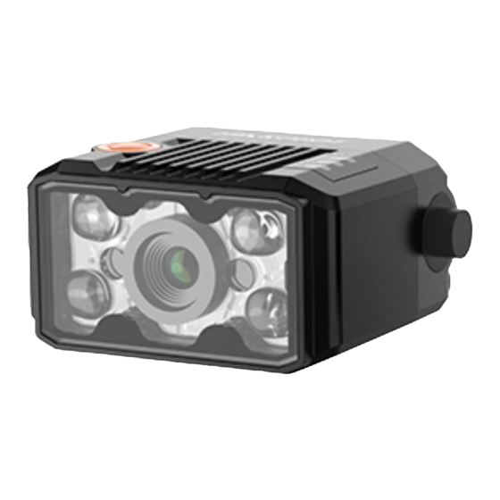
ID2000 Series Industrial Code Reader User Manual Chapter 1 Appearance Note Appearance here is for reference only. Refer to the device's specification for detailed dimension information. ● Type I device is a vari focal device that supports adjusting focus manually via its focus knob. - Page 13 ID2000 Series Industrial Code Reader User Manual Figure 1-2 Appearance (Type II) Figure 1-3 Appearance (Type III)
- Page 14 ID2000 Series Industrial Code Reader User Manual Figure 1-4 Appearance (Type IV) Table 1-1 Component Description Name Description It is used to adjust focal length manually. Focus Knob Note Only type I device has the focus knob. It is used to fix the device to the installation position.
- Page 15 ID2000 Series Industrial Code Reader User Manual Name Description It is a network status indicator. The indicator is flashing green when the network transmission is normal. Otherwise, it is unlit. LNK Indicator Note Type IV device does not have a LNK indicator.
-
Page 16: Chapter 2 Connector And Cable
ID2000 Series Industrial Code Reader User Manual Chapter 2 Connector and Cable This section introduces the device’s connector on its SR cable and the supplied cable in the package. Note The device’s connector and connector pin definitions may differ by device models. -
Page 17: Type I Device With Fast Ethernet Interface And Type Ii Device
ID2000 Series Industrial Code Reader User Manual 2.2 Type I Device with Fast Ethernet Interface and Type II Device Both type I device with fast Ethernet interface and type II device have a 17-pin M12 connector, but their corresponding connector pin definitions are different. Refer to the figure and table below for details. - Page 18 ID2000 Series Industrial Code Reader User Manual I/O Signal Supplied Cable Signal Description Source It can be configured as input Brown/white GPIO3 Line 3+ or output, and is output by open line default. Line 0/1/2/3- Direct current power supply Black open line...
- Page 19 ID2000 Series Industrial Code Reader User Manual I/O Signal Supplied Cable Signal Description Source line line IN_COM LineIn 0/1 Blue open line Input common port signal ground OPTO_OUT1 LineOut 1 signal Brown/white open Opto-isolated output 1 line line Direct current power...
-
Page 20: Type Iii Device
ID2000 Series Industrial Code Reader User Manual resistor. ● For type II device, the pink line in the open line is LineIn 0/1’s pull-up and pull-down resistor, and black/white line in the open line is LineOut 0/1’s pull-up and pull-down resistor. - Page 21 ID2000 Series Industrial Code Reader User Manual I/O Signal Supplied Cable Signal Description Source connector GPIO2 Line 2+ Blue/white open Non-isolated input line Blue open line GPIO3 Line 3+ Brown/white Non-isolated output open line Line 0/1/2/3- Direct current power supply...
-
Page 22: Type Iv Device With Fast Ethernet Interface
ID2000 Series Industrial Code Reader User Manual Figure 2-6 17-Pin Cable for Type III Device Note For type III device, black/white line in the open line is Line 0’s pull-up and pull-down resistor, pink line is Line 1’s pull-up and pull-down resistor, orange line is Line 2’s pull-up and pull- down resistor, and purple/white line is Line 3’s pull-up and pull-down resistor. - Page 23 ID2000 Series Industrial Code Reader User Manual Table 2-5 Pin Definitions (Type IV Device with Fast Ethernet Interface) I/O Signal Supplied Cable Signal Description Source Direct current power supply DB9 male serial POWER_IN -- positive port DB9 male serial RS232_TX...
-
Page 24: Type Iv Device With Usb Interface
ID2000 Series Industrial Code Reader User Manual Figure 2-8 Cable for Type IV Device with Fast Ethernet Interface Refer to the table below for the pin definitions of the 6-pin terminal. Table 2-6 Pin Definitions (6-Pin Terminal) Description LINEIN 0... - Page 25 ID2000 Series Industrial Code Reader User Manual Figure 2-9 DB15 Connector Table 2-7 Pin Definitions (Type IV Device with USB Interface) Signal I/O Signal Source Description Direct current power supply negative POWER_5IVN USB power interface USB_DM USB2.0 signal negative USB_DP USB2.0 signal positive...
-
Page 26: Chapter 3 Electrical Feature And I/O Wiring
ID2000 Series Industrial Code Reader User Manual Chapter 3 Electrical Feature and I/O Wiring 3.1 Electrical Feature and Wiring of Type I, III and IV Devices ● Type I device has four bi-directional I/O (Line 0/1/2/3). ● Type III device has two bi-directional I/O (Line 0/1), one input (Line 2), and one output (Line 3). -
Page 27: Output Signal
ID2000 Series Industrial Code Reader User Manual Parameter Name Parameter Symbol Value Input Falling Delay 200 ns Input Rising Delay 1 μs 3.1.2 Output Signal The internal circuit of the device’s none-isolated output signal is as follows. Figure 3-3 Internal Circuit of Output Signal... -
Page 28: Bi-Directional Signal
ID2000 Series Industrial Code Reader User Manual Table 3-3 Parameters of Output Logic Level Low Output Logic Level Low External Voltage (VL) 3.3 VDC 180 mV 5 VDC 260 mV 12 VDC 500 mV 24 VDC 900 mV 3.1.3 Bi-Directional Signal The type I device has four bi-directional I/O (Line 0/1/2/3) and the type III device has two bi- directional I/O (Line 0/1). - Page 29 ID2000 Series Industrial Code Reader User Manual Table 3-4 Input Electrical Feature Parameter Name Parameter Symbol Value Input Logic Level Low 1 VDC Input Logic Level High 2 VDC Input Falling Delay 200 ns Input Rising Delay 1 μs Configured as Output Signal...
-
Page 30: Input Signal Wiring
ID2000 Series Industrial Code Reader User Manual Output Logic Level Low External Voltage (VL) 12 VDC 500 mV 24 VDC 900 mV 3.1.4 Input Signal Wiring The device can receive the external input signal via I/O interface, and this section introduces input signal wiring. - Page 31 ID2000 Series Industrial Code Reader User Manual NPN Device If the VCC of NPN device is 12 VDC or 24 VDC, and the pull-up resistor of the supplied 17- pin cable is used. DB9 Connector Internal Resistor NPN Device Power ●...
-
Page 32: Output Signal Wiring
ID2000 Series Industrial Code Reader User Manual 3.1.5 Output Signal Wiring Note ● Output signal wiring may differ by external device types. ● The supplied 17-pin cable of type I and type III has pull-up and pull-down resistors, and type IV device’s supplied cable does not have pull-up and pull-down resistors. Here we take type I device as an example for introducing output signal wiring. -
Page 33: Electrical Feature And Wiring Of Type Ii Device
ID2000 Series Industrial Code Reader User Manual recommended to use 1 KΩ pull-up resistor. NPN Device Power DB9 Connector ● None-isolated ● Signal Line Output Device NPN Power Ground Output Signal Ground GND of VCC GND of PWR Figure 3-15 Output Signal Connecting to NPN Device (External Pull-Up Resistor Used) 3.2 Electrical Feature and Wiring of Type II Device... -
Page 34: Output Signal
ID2000 Series Industrial Code Reader User Manual Input Level High Input Level Low Internal Logic Figure 3-17 Input Logic Level Table 3-7 Input Electrical Feature Parameter Name Parameter Symbol Value Input Logic Level Low 1.5 VDC Input Logic Level High... -
Page 35: Input Signal Wiring
ID2000 Series Industrial Code Reader User Manual Internal Logic Output Level High Output Level Low Figure 3-19 Output Logic Level Table 3-8 Output Electrical Feature Parameter Name Parameter Symbol Value Output Logic Level Low 730 mV Output Logic Level High 3.2 VDC... -
Page 36: Output Signal Wiring
ID2000 Series Industrial Code Reader User Manual PNP Device PNP Device Power DB9 Connector Opto Input Signal Line Device Input Signal Ground PNP Power Ground GND of VCC GND of PWR Figure 3-20 Input Signal Connecting to PNP Device NPN Device If the VCC of NPN device is 12 VDC or 24 VDC, and the pull-up resistor of the supplied 17- pin cable is used. - Page 37 ID2000 Series Industrial Code Reader User Manual introduces output signal wiring. Note ● Output signal wiring may differ by external device types. ● The supplied 17-pin cable has pull-up and pull-down resistors. ● The voltage of VCC should be equal to or less than that of PWR. Otherwise, the output signal exception may occur.
-
Page 38: Serial Port
ID2000 Series Industrial Code Reader User Manual recommended to use 1 KΩ pull-up resistor. NPN Device Power DB9 Connector ● Opto Output ● Signal Line Device NPN Power Ground Output Signal Ground GND of VCC GND of PWR Figure 3-25 Output Signal Connecting to NPN Device (External Pull-Up Resistor Used) 3.3 RS-232 Serial Port... -
Page 39: Chapter 4 Installation
ID2000 Series Industrial Code Reader User Manual Chapter 4 Installation 4.1 Installation Preparation You need to prepare following accessories before installation. Table 4-1 Accessories Name Quantity Description It refers to the supplied cable that is included in the Cable package. Refer to section Connector and Cable for details. - Page 40 ID2000 Series Industrial Code Reader User Manual Note For type I device with USB interface, connect it to external devices that support USB3.0 for power supply and data transmission. ● For type IV device with fast Ethernet interface, connect the device to the supplied cable...
-
Page 41: Chapter 5 Device Connection
ID2000 Series Industrial Code Reader User Manual Chapter 5 Device Connection Device connection to the client software is required for device’s configuration and remote operations. This section introduces how to install the client software, set PC environment, connect the device to the client software, etc. -
Page 42: Set Pc Environment
ID2000 Series Industrial Code Reader User Manual 5.2 Set PC Environment To ensure stable client running and data transmission, you are recommended to set PC environment. For the network device, you need to turn off the firewall and set PC network. -
Page 43: Check Usb Drive For Usb Device
ID2000 Series Industrial Code Reader User Manual 1. Go to PC network settings page: Start → Control Panel → Network and Internet → Network and Sharing Center → Change adapter settings. 2. Select NIC and set the IP obtainment mode. -
Page 44: Set Device Network
ID2000 Series Industrial Code Reader User Manual 5.3 Set Device Network You can set and operate the device in the client software only when the device is in the same network segment with the PC where the client software is installed. -
Page 45: Chapter 6 Client Software Layout
ID2000 Series Industrial Code Reader User Manual Chapter 6 Client Software Layout After connecting to the device, the client software can read the device information and display it. Figure 6-1 Main Window Note The specific interfaces of the client software may differ by its versions. - Page 46 ID2000 Series Industrial Code Reader User Manual You can set device parameters in device configuration area. Figure 6-2 Device Configuration Area Table 6-2 Configuration Area Description Module Name Description You can connect or disconnect device, modify device Device Connection IP address, view device information, etc.
-
Page 47: Chapter 7 Device Mode Settings
ID2000 Series Industrial Code Reader User Manual Chapter 7 Device Mode Settings The device supports 3 types of operating modes, including Test, Normal, and Raw. You can select different modes in live view window according to actual demands. Note ● Stopping the real-time acquisition is required before selecting modes. - Page 48 ID2000 Series Industrial Code Reader User Manual Figure 7-2 Code Reading...
-
Page 49: Chapter 8 Device Settings
ID2000 Series Industrial Code Reader User Manual Chapter 8 Device Settings You are recommended to complete device settings in following order: Device Connection → Image Settings → Algorithm Settings → I/O Control Settings → Data Processing → Communication Settings → Configuration Management. - Page 50 ID2000 Series Industrial Code Reader User Manual frame rate, acquisition burst frame count in image parameters interface. Note ● Make sure you have select the device to be set in Device Connection before setting image parameters. ● For specific parameter range like exposure time, gain and acquisition frame rate, refer to the device's specification for details.
-
Page 51: Set Polling
ID2000 Series Industrial Code Reader User Manual Figure 8-1 Set Image 8.1.2 Set Polling The polling function allows the device to acquire images based on the parameters you set, including exposure time, gain, Gamma, light source, focus position, etc. Currently, 2 types of polling modes are available, including single mode and multiple mode. - Page 52 ID2000 Series Industrial Code Reader User Manual Figure 8-2 Single Mode Multiple Mode Note ● In multiple mode, the device supports trigger parameters like software trigger, external trigger, TCP, etc., does not support stopping polling via the external trigger. ● The parameter of Best Polling Group Idx is used to display the polling parameter number when the device recognizes codes after enabling polling.
- Page 53 ID2000 Series Industrial Code Reader User Manual ● Polling Focus Temp: It displays the device’s current temperature when setting the focus position. 8. Repeat step 4 to step 7 to set other parameters from Polling Param. 9. Go to Stop Trigger Control → Polling Stop Trigger Enable, enable Polling Stop Trigger Enable, and set stop condition of the polling.
-
Page 54: Set Light Source
ID2000 Series Industrial Code Reader User Manual Parameter 1 Parameter 4 Parameter 3 Parameter 2 Exposure Time 1 Exposure Time 4 Exposure Time 2 Exposure Time 3 Gain 1 Gain 4 Gain 3 Gain 2 Gamma 1 Gamma 4 Gamma 3... -
Page 55: Set Lens Focus
ID2000 Series Industrial Code Reader User Manual 8.1.4 Set Lens Focus The type III device adopts the high-speed vari focal lens, and it can complete single focus adjustment in 5 ms. The device also supports focus adjustment via external devices, and it is applicable to the mixed line production. - Page 56 ID2000 Series Industrial Code Reader User Manual Note The area focus is applicable to the scenario where the image has codes with different depth of fields. 3. Go to Focus Control → Auto Config, and select the focus mode according to actual demands.
- Page 57 ID2000 Series Industrial Code Reader User Manual ● Motor Only: In this mode, the device will change focus position only when adjusting focus. ● Auto and Restore: In this mode, the device will automatically change parameters like focus position, exposure, gain, Gamma and light source when adjusting focus, and keep focus position and restore other parameters after completing focus adjustment.
- Page 58 ID2000 Series Industrial Code Reader User Manual Figure 8-10 Adjust Focus via External Devices 4. (Optional) Set TCP Focus Port if TCP is selected as Focus Label Source. Figure 8-11 Set TCP Focus Port 5. (Optional) Set UDP Focus Port if UDP is selected as Focus Label Source.
-
Page 59: Set Self-Adaptive Adjustment
ID2000 Series Industrial Code Reader User Manual 6. (Optional) Set Serial Baudrate, Serial Data Bits, Serial Parity, and Serial Stop Bits if Serial is selected as Focus Label Source. Figure 8-13 Serial Related Parameters 7. Enable Focus Label Valid after settings, and external devices can control the device to adjust focus via sending trigger commands. -
Page 60: Set Mirror X
ID2000 Series Industrial Code Reader User Manual ● Polling Param: It adjusts parameters configured in polling. After Polling Param is selected as Param Source, you can select polling parameter group from Polling Param, and enable Apply Polling Focus to adjust polling focus according to actual demands. -
Page 61: Set Test Pattern
ID2000 Series Industrial Code Reader User Manual according to actual demands. Note This function is enabled by default, and it may differ by device models. 8.1.7 Set Test Pattern Test pattern helps troubleshooting image problems and images in the test pattern are only for test. -
Page 62: Set Code Reading Roi
ID2000 Series Industrial Code Reader User Manual Figure 8-15 Add Codes 8.2.2 Set Code Reading ROI Algorithm ROI (Region of Interest) allows the device to execute algorithms and read codes on the specific area you selected, and thus improving code reading efficiency. - Page 63 ID2000 Series Industrial Code Reader User Manual Draw Single Group of ROI Steps 1. Go to Algorithm Settings, click All Features, and find Algorithm ROI. 2. Click Draw to draw ROI in the live view window. 3. (Optional) Repeat the above step to draw multiple ROIs according to actual demands.
- Page 64 ID2000 Series Industrial Code Reader User Manual 4. Repeat other optional steps mentioned in drawing single group of ROI according to actual demands. 5. (Optional) Enable ROI Link IO Enable in Algorithm ROI, and there will be prompts by the output device when codes are not read in any ROI.
- Page 65 ID2000 Series Industrial Code Reader User Manual Figure 8-17 Create Chessboard ROI 3. Click after creating ROI, and the red frame becomes green as shown below. Figure 8-18 Draw ROI via Chessboard 4. (Optional) Click to restore the ROI to the full screen, and click to clean all configured ROIs.
-
Page 66: Set 1D Algorithm Parameter
ID2000 Series Industrial Code Reader User Manual 8.2.3 Set 1D Algorithm Parameter Click All Features on the upper-right to display all algorithm parameters. In the Algorithm Parameter page, select 1DCode as Arithmetic Type, and then you can set its corresponding parameters. - Page 67 ID2000 Series Industrial Code Reader User Manual corresponding parameters. Note ● You should have selected at least one type of 2D code. ● For different models of the device, the specific parameters may differ, and the actual device you purchased shall prevail.
- Page 68 ID2000 Series Industrial Code Reader User Manual black. Figure 8-19 White QR Code Figure 8-20 Black QR Code ● For DM code, the code color is determined by the color of its "L" shaped sides. White "L" shaped sides indicate that the code color is white, and black "L" shaped sides indicate that the code color is black.
-
Page 69: Set 2D Code Quality Evaluation
ID2000 Series Industrial Code Reader User Manual continuous, or the minimum units in the concentric square like in the QR code are continuous. Usually the continuous code uses squares as the minimum units. Discrete stands for the minimum units in the "L" shaped sides of the DM code are... -
Page 70: Set Code Score
ID2000 Series Industrial Code Reader User Manual Note ● The function of code quality evaluation may differ by device models. ● In test mode, this function is enabled by default. In normal mode, you need to enable it manually. Steps 1. -
Page 71: Line Mode Settings
ID2000 Series Industrial Code Reader User Manual it has read. Note ● The function of code score may differ by device models. ● In test mode, this function is enabled by default. In normal mode, you need to enable it manually. -
Page 72: Signal Input Settings
ID2000 Series Industrial Code Reader User Manual Go to I/O Control Settings → Line Mode Control, and set Input or Output according to actual demands. Note ● Only the vari focal device supports this function. ● If the device has 4 bi-directional I/Os, and Line 0 and Line 1 are input, and Line 2 and Line 3 are output by default. -
Page 73: Enable Internal Trigger Mode
ID2000 Series Industrial Code Reader User Manual 8.4.2 Enable Internal Trigger Mode In the internal trigger mode, the device acquires images via its internal signals. You have 2 methods to enable the internal trigger mode: ● Click I/O Control Settings → Input → Trigger Mode, and select Off as Trigger Mode. - Page 74 ID2000 Series Industrial Code Reader User Manual 3. Select the specific line as Trigger Source according to actual demands. Note For the vari focal device, you can select customized lines as Trigger Source. Refer to section Line Mode Settings for specific settings.
- Page 75 ID2000 Series Industrial Code Reader User Manual Figure 8-29 Set and Execute Counter Trigger Mode Set and Execute TCP Trigger Mode TCP start specifies the TCP server as the source for the trigger signal. When the server receives the specified string text, the trigger signal will be outputted.
- Page 76 ID2000 Series Industrial Code Reader User Manual Figure 8-31 Set and Execute UDP Trigger Mode Set and Execute Serial Port Trigger Mode Serial start specifies the serial port as the source for the trigger signal. When the serial port receives the specified string text, the trigger signal will be outputted.
- Page 77 ID2000 Series Industrial Code Reader User Manual USB Parity, USB Stop Bits, and USB Start Trigger Text according to actual demands. Figure 8-33 Set and Execute USB Trigger Mode Note You need to go to Feature Tree, find Trigger IO Control, and set USB Start as Trigger Source.
-
Page 78: Stop Trigger
ID2000 Series Industrial Code Reader User Manual 8.4.4 Stop Trigger The device supports stopping trigger via TCP, UDP, I/O, serial port and USB. You can also set code reading timeout duration or max. code amount to be read to stop trigger. After stopping trigger is completed, the device cannot make response to trigger again. - Page 79 ID2000 Series Industrial Code Reader User Manual Stop Trigger via IO You can stop a trigger via IO: Enabling IO Stop Trigger Enable first, select specific sources from IO Stop Trigger Selector, and then set the trigger polarity as the condition to stop trigger.
- Page 80 ID2000 Series Industrial Code Reader User Manual Figure 8-39 Stop Trigger via Serial Port Stop Trigger via USB The USB stop trigger function means that the device receives USB commands from the external device to stop image acquisition. At this time, the device acts as a USB server to receive commands, and the external device communicating with it acts as a USB client to send commands.
- Page 81 ID2000 Series Industrial Code Reader User Manual Stop Trigger via Timeout Duration Note TimeOut Stop Trigger Enable is only available when the camera mode is set to Normal and the Trigger Mode is On. When the trigger time reaches the specified maximum value (in ms), the trigger will be stopped.
-
Page 82: Signal Output Settings
ID2000 Series Industrial Code Reader User Manual 8.5 Signal Output Settings 8.5.1 Select Output Signal The device’s output signal can control external devices like PLC, flashing light, etc. Click I/O Control Settings → Output → Line Out Selector to select output signal. -
Page 83: Set Event Source
ID2000 Series Industrial Code Reader User Manual 8.5.3 Set Event Source The device supports outputting different trigger signals according to the event source you select. Click I/O Control Settings → Output → Line Out Activation Event to select event source. - Page 84 ID2000 Series Industrial Code Reader User Manual Figure 8-45 Select No Code Read Select Read Success If you select ReadSuccess as Line Out Activation Event, you can set its output delay time and duration. Line Out Delay Time It sets the delay time for outputting the output signal.
- Page 85 ID2000 Series Industrial Code Reader User Manual Line Out Duration It sets the time duration of the output signal. Figure 8-47 Select Compare Success Select Compare Fail If you select Compare Fail as Line Out Activation Event, you can set its output delay time and duration.
-
Page 86: Set Buzzer
ID2000 Series Industrial Code Reader User Manual 8.5.4 Set Buzzer Note ● Only type IV device supports buzzer function. ● Make sure that the device is the Normal mode before using the buzzer function. The buzzer is used to indicate the device’s operation status, and you can set the buzzer function according to actual demands. -
Page 87: Set Filter Rule
ID2000 Series Industrial Code Reader User Manual Rule. Within the configured Filter Time, the device will not output any code information. Note The filter rule and data processing parameters may differ with different device modes and trigger modes. 8.6.2 Set Filter Rule You can set rules to filter unwanted codes to improve the reading efficiency in Filter Rule. - Page 88 ID2000 Series Industrial Code Reader User Manual Code Offset Num It sets the range of barcode to be filtered. For example, the barcode is ABCDEFG, if you set this parameter as 2, the device will output CDEFG at last and filter AB.
- Page 89 ID2000 Series Industrial Code Reader User Manual If it is enabled, the device will filter information based on drawn ROIs. Code Start Offset Num It cuts the specific length of code contents from starting, and the remaining part will be outputted.
- Page 90 ID2000 Series Industrial Code Reader User Manual Figure 8-51 Enter Customized Regular Expression Filter Rules Table 8-1 Filter Rule Parameters Parameter Description Name The default rule name is Rule 1, and you can edit it according to actual Rule Name demands.
- Page 91 ID2000 Series Industrial Code Reader User Manual Parameter Description Name Note If multiple characters are used, code meeting one of these characters is valid. It excludes the specific end with code. You can use semicolon to separate if there are multiple characters.
-
Page 92: Set Result Format
ID2000 Series Industrial Code Reader User Manual Note If the filter rule you configured is correct, the result is valid. Otherwise, it is invalid. 4. (Optional) Click to delete unwanted filter rules. 5. (Optional) Click Export to export configured filter rules to local PC. - Page 93 ID2000 Series Industrial Code Reader User Manual If it is enabled, the device will send one piece of code information each time in accordance with the specified interval. You can set the interval via One By One Interval and the default value 100 ms.
- Page 94 ID2000 Series Industrial Code Reader User Manual The contents of the end part of the data outputted. You can set the contents according to actual condition. TCP Output Barcode Enter Character Enable If it is enabled, carriage return will be added at the last of a trigger number.
- Page 95 ID2000 Series Industrial Code Reader User Manual Note The device currently support JPG format only. FTP File Default Name It refers to the default name of the file uploaded to FTP server. You can set it according to actual condition.
- Page 96 ID2000 Series Industrial Code Reader User Manual example, if you set this parameter as 5, and the 5th image will be output. One By One Enable If it is enabled, the device will send one piece of code information each time in accordance with the specified interval.
-
Page 97: Communication Settings
ID2000 Series Industrial Code Reader User Manual 8.7 Communication Settings The communication protocol is used to transmit and output code reading result and image. The communication protocol is related to the device modes. With various device modes, the device supports different communication protocols and corresponding parameters. -
Page 98: Serial
ID2000 Series Industrial Code Reader User Manual If enabled, when the TCP server is abnormal, the device will cache the images. When the server returns to normal, the device will send the cached images to the server. After this parameter being enabled, you can set Output Result Buffer Number to determine the number of the images that the device will cache. -
Page 99: Tcp Server
ID2000 Series Industrial Code Reader User Manual If enabled, when the FTP server is abnormal, the device will cache the images. When the FTP server returns to normal, the device will send the cached images to the server. After this parameter being enabled, you can set Output Result Buffer Number to determine the number of the images that the device will cache. -
Page 100: Melsec Or Slmp
ID2000 Series Industrial Code Reader User Manual Figure 8-58 Profinet 8.7.7 MELSEC or SLMP If MELSEC or SLMP is selected as the Communication Protocols, you can set related parameters according to actual demands. MELSEC Server IP It sets the IP address of MELSEC server. - Page 101 ID2000 Series Industrial Code Reader User Manual It sets storage space of the control area. MELSEC Control Offset It sets the start offset address of the control area. MELSEC Control Size (Word) It sets the size of the control area.
-
Page 102: Ethernet/Ip
ID2000 Series Industrial Code Reader User Manual Figure 8-59 MELSEC 8.7.8 Ethernet/IP If Ethernet/IP is selected as the Communication Protocols, you can enable Ethernet/IP Enable, and the device will output data via Ethernet/IP. You can set Ethernet/IP Input Assembly Size (Word), Ethernet/IP Output Assembly Size (Word), Ethernet/IP Result Byte... -
Page 103: Modbus
ID2000 Series Industrial Code Reader User Manual Figure 8-60 Ethernet/IP 8.7.9 ModBus If ModBus is selected as the Communication Protocols, you can enable ModBus Enable and set related parameters according to actual demands. ModBus Mode It includes server and client, and is server by default. -
Page 104: Udp
ID2000 Series Industrial Code Reader User Manual ModBus Result Size (Word) It sets max. length of ModBus result. It is 100 by default. ModBus Result Byte Swap If it is enabled, the client software will swap ModBus results. ModBus Result Timeout (s) It sets the ModBus result timeout, and the unit is s. -
Page 105: Fins
ID2000 Series Industrial Code Reader User Manual Figure 8-62 UDP 8.7.11 Fins If Fins is selected as the Communication Protocols, you can enable Fins Enable and set related parameters according to actual demands. Fins Server IP It sets the server IP of Fins. -
Page 106: Usb
ID2000 Series Industrial Code Reader User Manual Fins Result Size (Word) It sets the size of the result area. Fins Result Byte Swap If it is enabled, the client software will swap Fins results. Fins Result Timeout (s) It sets the Fins result timeout, and the unit is s. - Page 107 ID2000 Series Industrial Code Reader User Manual Figure 8-64 USB Some device models support setting USB communication parameters via reading setting codes. You need to let the device read the code of starting settings to enable the function, and read the code of ending settings to disable the function.
-
Page 108: Set Multicast
ID2000 Series Industrial Code Reader User Manual Table 8-2 USB Setting Codes Setting Codes Function Setting Codes Function Enable USB HID Enable USB communication mode communicatio n mode 8.8 Set Multicast The multicast function is used to let multiple devices have the same trigger number when they are acquiring images and analyzing codes at the same time. -
Page 109: Main-Sub Networking
ID2000 Series Industrial Code Reader User Manual 8.9 Main-Sub Networking When multiple devices acquire images and parse codes at the same time, the main-sub networking function enables multiple devices to work together. The main principle of main-sub networking is to set one of the multiple devices as the main device (main station), and the other devices as sub devices (sub station). - Page 110 ID2000 Series Industrial Code Reader User Manual 5. Set MS Group ID ranging from 100 to 200 to configure the main-sub networking group Note Two-way visiting is not allowing among different network groups. 6. (Optional) View enumerated sub station quantity via Sub Station Total as a main station role.
-
Page 111: Contrast Control Settings
ID2000 Series Industrial Code Reader User Manual 8.10 Contrast Control Settings Note You need to set device mode as Normal before using this function. The contrast control function compares the data that the device reads with preset data and outputs contrast result. The result can be used as the event source of trigger signal, including Contrast Success and Contrast Fail. - Page 112 ID2000 Series Industrial Code Reader User Manual result. Steps 1. Right click the device in Device Connection, and click Feature Tree. 2. Go to Contrast Control, enable Contrast Enable, and select Consecutive Number as Compare Rules. 3. Set Start Position that means the stating position of the comparison.
-
Page 113: Statistics Information
ID2000 Series Industrial Code Reader User Manual 8.11 Statistics Information The statistics information in the feature tree helps you to count data related with code reading. Note You need to set device mode as Normal before using this function. Go to feature tree, find Statistics Info., and select Statistics Mode according to actual demands. -
Page 114: Event Report
ID2000 Series Industrial Code Reader User Manual Figure 8-71 Statistics Information 8.12 Event Report The diagnose event report function in the feature tree monitors memory and CPU usage rate, and let you know when there is a crash, higher CPU usage rate, insufficient memory, and other events. -
Page 115: User Set Customization
ID2000 Series Industrial Code Reader User Manual 8.13 User Set Customization The Configuration Management module allows you to set and manage the user set. A user set is a group of parameter values with all the settings needed to control the device, and you can save, load and switch different user sets. -
Page 116: Chapter 9 Device Operation
ID2000 Series Industrial Code Reader User Manual Chapter 9 Device Operation The device operation section introduces some basic device operations about how to start live view, acquisition and recording, add cross line in the image, split window, view reports, etc. -
Page 117: Add Cross Line
ID2000 Series Industrial Code Reader User Manual Figure 9-2 Enable Acquisition 9.3 Add Cross Line During live view, you can add a cross line on the live view image to adjust the position of the object in the view. Click... -
Page 118: Split Window
ID2000 Series Industrial Code Reader User Manual Figure 9-4 Start Recording 9.5 Split Window The client software supports window division function that allows you to split the window into multiple-window mode to view the live view of multiple devices at the same time. -
Page 119: View Log
ID2000 Series Industrial Code Reader User Manual Figure 9-6 View Reports 9.7 View Log You can view the device logs and export them to the local PC. Click in control toolbar to open the device log window, and you can view different types of logs, including device errors, warning, and informational log, etc. -
Page 120: Enable Device Auto Work
ID2000 Series Industrial Code Reader User Manual Figure 9-8 Set NTP Timing 9.9 Enable Device Auto Work This function allows the device to automatically enter the operating status after being powered on. You can go to Config Management → Device Auto Work Enable, and enable Device Auto Work Enable. -
Page 121: Chapter 10 Device Maintenance
ID2000 Series Industrial Code Reader User Manual Chapter 10 Device Maintenance 10.1 Update Firmware The device supports updating firmware via the client software. Note ● Disconnect the device with client software. ● Please use the firmware package of the corresponding device model for upgrading. - Page 122 ID2000 Series Industrial Code Reader User Manual Figure 10-2 Reboot Device...
-
Page 123: Chapter 11 Faq (Frequently Asked Question)
ID2000 Series Industrial Code Reader User Manual Chapter 11 FAQ (Frequently Asked Question) 11.1 Why the image is very dark? Problem All black or too dark during preview. Reason Too small adjustment value of exposure and gain. Solution Increase exposure and gain appropriately. -
Page 124: Why There Is No Image In The Live View
ID2000 Series Industrial Code Reader User Manual Solution ● Check the device power connection (observe whether the PWR light is solid green or not) to make sure that the device is powered up normally. ● Check the network connection (observe whether the LNK light is flashing green or not) to make sure the device can be connected to the network normally, and the PC network and the device are in the same network segment. - Page 125 UD29484B...
Need help?
Do you have a question about the ID2000 Series and is the answer not in the manual?
Questions and answers