Table of Contents
Advertisement
Advertisement
Table of Contents

Related Manuals for HikRobot ID3000 Series


Summary of Contents for HikRobot ID3000 Series
- Page 1 ID3000 Series Smart Code Reader User Manual...
- Page 2 INTERRUPTION, OR LOSS OF DATA, CORRUPTION OF SYSTEMS, OR LOSS OF DOCUMENTATION, WHETHER BASED ON BREACH OF CONTRACT, TORT (INCLUDING NEGLIGENCE), PRODUCT LIABILITY, OR OTHERWISE, IN CONNECTION WITH THE USE OF THE PRODUCT, EVEN IF HIKROBOT HAS BEEN ADVISED OF THE POSSIBILITY OF SUCH DAMAGES OR LOSS.
- Page 3 ID3000 Series Smart Code Reader User Manual ABUSES. THE PERFORMANCE DATA IN THIS PUBLICATION IS BASED ON HIKROBOT'S INTERNAL RESEARCH/EVALUATION. ACTUAL DATA MAY VARY DEPENDING ON SPECIFIC CONFIGURATIONS AND OPERATING CONDITIONS AND HIKROBOT SHALL NOT BEAR THE CONSEQUENCES ARISING THEREFROM.
- Page 4 Note important points of the main text. Available Model This manual is applicable to the ID3000 Series Smart Code Reader. Safety Instruction These instructions are intended to ensure that the user can use the product correctly to avoid danger or property loss.
- Page 5 ID3000 Series Smart Code Reader User Manual Transportation ● The product contains precision optical components and electronic components. During transportation, storage and installation, incorrect operations like heavy pressure and violent vibration should be avoided. Otherwise, the product may be damaged.
- Page 6 ID3000 Series Smart Code Reader User Manual problems arise, the product can be packed with packaging materials and sent to the agent or returned to the manufacturer for processing. The company does not bear any liability for accidental damage during transportation caused by non-original packaging.
-
Page 7: Table Of Contents
ID3000 Series Smart Code Reader User Manual Contents Chapter 1 Appearance ........................ 1 Chapter 2 Interface Description ....................3 Chapter 3 I/O Wiring ........................5 3.1 Input Signal ..........................5 3.2 Output Signal ......................... 6 3.3 Input Signal Wiring ........................ 7 3.4 Output Signal Wiring ...................... - Page 8 ID3000 Series Smart Code Reader User Manual 8.2.3 Set 2D Algorithm Parameter ..................30 8.2.4 Set Code Reading ROI ....................33 8.3 Signal Input Settings ......................34 8.3.1 Set Trigger Mode ...................... 34 8.3.2 Enable Internal Trigger Mode .................. 34 8.3.3 Enable External Trigger Mode .................
- Page 9 ID3000 Series Smart Code Reader User Manual 9.4 Start Recording ........................73 9.5 Split Window ........................74 9.6 View Reports ........................74 9.7 View Log ..........................75 9.8 Enable Camera Auto Work ....................75 Chapter 10 Camera Maintenance ..................... 76 10.1 Update Firmware.......................
-
Page 10: Chapter 1 Appearance
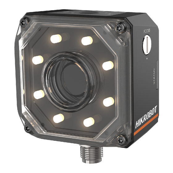
Note Appearance here is for reference only. Refer to the device's specification for detailed dimension information. Currently, ID3000 series smart code reader has 2 types, including manual focus device and mechanical focus device. Figure 1-1 Appearance Table 1-1 Appearance Description... - Page 11 ID3000 Series Smart Code Reader User Manual Name Description It indicates code reading result. ● The indicator is orange when the device is starting up. OK/NG Indicator ● The indicator is red after the device is powered on. ● The indicator is flashing green after the device reads barcodes, and it is solid green if the device reads barcodes continuously.
-
Page 12: Chapter 2 Interface Description
ID3000 Series Smart Code Reader User Manual Chapter 2 Interface Description Read the following section to get definitions of 17-pin interface. Figure 2-1 17-Pin Interface Table 2-1 Pin Definitions Signal I/O Signal Source Description POWER_IN Direct current power supply positive... - Page 13 ID3000 Series Smart Code Reader User Manual Signal I/O Signal Source Description DI_0 LineIn0 signal line Input DI_1 LineIn1 signal line Input Note ● You should refer to the table above and the label attached to the power and I/O cable to wire the device.
-
Page 14: Chapter 3 I/O Wiring
ID3000 Series Smart Code Reader User Manual Chapter 3 I/O Wiring 3.1 Input Signal The device's LineIn 0/1/2 are input signals, and their internal circuit is as follows. Note ● The maximum input current of input signal is 25 mA. -
Page 15: Output Signal
ID3000 Series Smart Code Reader User Manual Table 3-1 Input Electrical Feature Parameter Name Parameter Symbol Value 0 VDC to 9 VDC (VCC=24 VDC) Input Logic Level Low 0 VDC to 5.4 VDC (VCC=12 VDC) 11 VDC to 24 VDC (VCC=24 VDC) Input Logic Level High 7.56 VDC to 12 VDC (VCC=12 VDC) -
Page 16: Input Signal Wiring
ID3000 Series Smart Code Reader User Manual Figure 3-4 Output Logic Level When the external voltage and resistance is 12 VDC and 1 KΩ respectively, output electrical feature is as follows. Note If the external voltage and resistance change, the corresponding current of output signal and output logic level low may differ. - Page 17 ID3000 Series Smart Code Reader User Manual PNP Device Note It is recommended to use 330 Ω pull-down resistor. Figure 3-5 Input Signal Connecting to PNP Device NPN Device Note If the VCC of NPN device is 12 VDC or 24 VDC, and it is recommended to use 1 KΩ pull-up resistor.
-
Page 18: Output Signal Wiring
ID3000 Series Smart Code Reader User Manual Figure 3-7 Input Signal Connecting to a Switch 3.4 Output Signal Wiring The device can output signal to external devices via I/O interface, and here we take LineOut 0 as an example to introduce output signal wiring. -
Page 19: Rs-232 Serial Port
ID3000 Series Smart Code Reader User Manual Figure 3-9 Output Signal Connecting to NPN Device 3.5 RS-232 Serial Port The 9-pin male connector and 25-pin male connector are commonly used serial ports, as shown below. You can refer to the table below for the specific pin name and function. - Page 20 ID3000 Series Smart Code Reader User Manual You can refer to the serial port wiring below to connect the device with an external device. Device Power RS-232 Serial Port External Output Device RS-232 Serial Port Input Device Power Ground Figure 3-12 RS-232 Serial Port Wiring...
-
Page 21: Chapter 4 Installation
ID3000 Series Smart Code Reader User Manual Chapter 4 Installation 4.1 Installation Preparation You need to prepare following accessories before installation. Table 4-1 Accessories Name Quantity Description It refers to the supplied 17-pin cable that is 17-Pin Cable included in the package. -
Page 22: Install Client Software
ID3000 Series Smart Code Reader User Manual 4.3 Install Client Software IDMVS is a client software for camera configuration and remote operations. Steps Note ● Check the Windows version. The client software is compatible with 32/64-bit Windows XP/7/10. ● You can get the client software installation package from https://en.hikrobotics.com/. - Page 23 ID3000 Series Smart Code Reader User Manual Windows firewall before using the client software. Steps Note For different Windows versions, the path name or interface may differ. Please refer to the actual condition. 1. Go to Windows Firewall. Windows XP system: Click Start → Control Panel → Security Center → Windows Firewall.
-
Page 24: Chapter 5 Network Settings
ID3000 Series Smart Code Reader User Manual Chapter 5 Network Settings 5.1 Set PC Network To ensure stable image transmission and normal communication between the PC and the camera via client software, you need to set the PC network before using the client software. -
Page 25: Set Camera Network
ID3000 Series Smart Code Reader User Manual 5.2 Set Camera Network You can set and operate the camera in the client software only when the camera is in the same network segment with the PC where the client software is installed. -
Page 26: Chapter 6 Client Software Layout
ID3000 Series Smart Code Reader User Manual Chapter 6 Client Software Layout After connecting to the device, the client software can read the device information and display it. Figure 6-1 Main Window Note The specific interfaces of the client software may differ by its versions. - Page 27 ID3000 Series Smart Code Reader User Manual You can set device parameters in device configuration area. Figure 6-2 Device Configuration Area Table 6-2 Description Module Name Description You can connect or disconnect device, modify device IP Device Connection address, view device information, etc.
-
Page 28: Chapter 7 Camera Mode Settings
ID3000 Series Smart Code Reader User Manual Chapter 7 Camera Mode Settings The device supports 3 types of operating modes, including Test, Normal, and Raw. You can select different modes in live view window according to actual demands. Note ● Stopping the real-time acquisition is required before selecting modes. - Page 29 ID3000 Series Smart Code Reader User Manual Figure 7-2 Code Reading...
-
Page 30: Chapter 8 Camera Settings
ID3000 Series Smart Code Reader User Manual Chapter 8 Camera Settings You are recommended to complete camera settings in following order: Device Connection → Image Settings → Algorithm Settings → I/O Control Settings → Data Processing → Communication Settings → Configuration Management. - Page 31 ID3000 Series Smart Code Reader User Manual Set Image Parameters You can set different image parameters like exposure time, gain, Gamma, acquisition frame rate, acquisition burst frame count in image parameters interface. Note ● Make sure you have select the camera to be set in Device Connection before setting image parameters.
- Page 32 ID3000 Series Smart Code Reader User Manual Figure 8-1 Set Image Set Parameters for Polling Function The polling function allows the device to acquire images based on the parameters you set, including exposure time, gain, Gamma, and light source. Currently, 2 types of polling modes are available, including single mode and multiple mode.
- Page 33 ID3000 Series Smart Code Reader User Manual Figure 8-2 Single Mode Multiple Mode Note ● The parameter of Best Polling Group Idx is used to display the polling parameter number when the device recognizes codes after enabling polling. If the polling is disabled or polling parameters are edited, it displays 1 by default.
-
Page 34: Set Light Source
ID3000 Series Smart Code Reader User Manual Figure 8-3 Multiple Mode Parameter 1 Parameter 4 Parameter 3 Parameter 2 Exposure Time 1 Exposure Time 4 Exposure Time 3 Exposure Time 2 Gain 1 Gain 4 Gain 3 Gain 2 Gamma 1... - Page 35 ID3000 Series Smart Code Reader User Manual You can select different light sources in Light Type. Own Lighting It refers to use the device's embedded light source to light during code reading. External Lighting It refers to the device controls the external light source by triggering output signal during code reading.
-
Page 36: Set Auto Focus
ID3000 Series Smart Code Reader User Manual Figure 8-5 Light Parameters If you select External Lighting as Light Type, you can set the following parameters. Line Out Duration The lighting duration of the external light source and the unit is μs. -
Page 37: Set Mirror X
ID3000 Series Smart Code Reader User Manual 3. Select the position parameter from Focus Position, and click Execute in Focus Position Save to save the focus position. 4. (Optional) Select the position parameter from Focus Position, and click Execute in Focus Position Load to load saved focus position. -
Page 38: Barcode Algorithm Settings
ID3000 Series Smart Code Reader User Manual 8.2 Barcode Algorithm Settings The code reader supports reading multiple types of 1D code and 2D code, and you can add and set code parameters via the client software. 8.2.1 Add Barcode Adding barcode before you set code parameters via the client software. In Algorithm Settings, you can add different types of barcodes, including Code 39, Code 93, Code 128, CodaBar, EAN, ITF 25, MATRIX 25, MSI, Industrial 25, China Post, QR Code, Data Matrix, etc. -
Page 39: Set 2D Algorithm Parameter
ID3000 Series Smart Code Reader User Manual Figure 8-7 Set 1D Algorithm Parameter 8.2.3 Set 2D Algorithm Parameter Click All Features on the upper-right to display all algorithm parameters. In the Algorithm Parameter page, select 2D Code as Arithmetic Type, and then you can set its corresponding parameters. - Page 40 ID3000 Series Smart Code Reader User Manual Note Increasing this parameter value will improve the code reading efficiency at the cost of code recognition rate. Code Color It defines the readable code color. Adaptive means that the client software can recognize both the black code with white background, and the white code with black background.
- Page 41 ID3000 Series Smart Code Reader User Manual Figure 8-10 White DM Code Figure 8-11 Black DM Code Discrete Flag Continuous stands for the minimum units in the "L" shaped sides of the DM code are continuous, or the minimum units in the concentric square like in the QR code are continuous.
-
Page 42: Set Code Reading Roi
ID3000 Series Smart Code Reader User Manual Code Quality Evaluation Enable If it is enabled, the device will evaluate the Data Matrix code quality and display overall grade and code score in the history record area of the client software. The higher the score, and the better the Data Matrix code quality. -
Page 43: Signal Input Settings
ID3000 Series Smart Code Reader User Manual Go to Algorithm Settings, click All Features, find Algorithm ROI, select ROI from ROI Selector, and enable ROI Enable. Click Draw to draw the ROI in the live view window, or set Draw ROI Width, Draw ROI Height, Draw ROI Offset X and Draw ROI Offset Y according to actual demands, and you can right click the drawn ROI, and click Delete to delete it. -
Page 44: Enable External Trigger Mode
ID3000 Series Smart Code Reader User Manual ● Click I/O Control Settings → Input → Trigger Mode, and select Off as Trigger Mode. ● In the live view page, click to enable the internal trigger mode. 8.3.3 Enable External Trigger Mode In the external trigger mode, the camera acquires images via external signals like software signal and hardware signal. - Page 45 ID3000 Series Smart Code Reader User Manual Note ● When selecting Rising Edge or Falling Edge as Line Out Trigger In Polarity, you can set Trigger Delay. ● When selecting Level High or Level Low as Line Out Trigger In Polarity, you can set Start Delay Time and End Delay Time according to actual demands.
- Page 46 ID3000 Series Smart Code Reader User Manual Figure 8-16 Set and Execute Counter Trigger Mode Set and Execute TCP Trigger Mode TCP start specifies the TCP server as the source for the trigger signal. When the server receives the specified string text, the trigger signal will be outputted.
-
Page 47: Stop Trigger
ID3000 Series Smart Code Reader User Manual Figure 8-18 Set and Execute UDP Trigger Mode Set and Execute Serial Port Trigger Mode Serial start specifies the serial port as the source for the trigger signal. When the serial port receives the specified string text, the trigger signal will be outputted. - Page 48 ID3000 Series Smart Code Reader User Manual completed, the device cannot make response to trigger again. Stop Trigger via IO You can stop a trigger via IO: Enabling IO Stop Trigger Enable first, select specific sources from IO Stop Trigger Selector, and then set the trigger polarity as the condition to stop trigger.
- Page 49 ID3000 Series Smart Code Reader User Manual Figure 8-22 Stop Trigger via Serial Stop Trigger via UDP When the UDP server receives the specified string text, the trigger will be stopped. The client software sends stop trigger command to the device after Udp Stop Trigger Enable is enabled. You should enter Udp Trigger Port and Udp Stop Trigger Text according to actual demands.
- Page 50 ID3000 Series Smart Code Reader User Manual Figure 8-24 Stop Trigger via TCP Stop Trigger via Timeout Duration Note TimeOut Stop Trigger Enable is only available when the camera mode is set to Normal and the Trigger Mode is On.
-
Page 51: Signal Output Settings
ID3000 Series Smart Code Reader User Manual outputting codes when the number of outputted codes reaches the configured number. Figure 8-26 Stop Trigger via Code Number 8.4 Signal Output Settings 8.4.1 Select Output Signal The device’s output signal can control external devices like PLC, flashing light, etc. Click I/O Control Settings →... -
Page 52: Set Event Source
ID3000 Series Smart Code Reader User Manual Figure 8-28 Enable Line Out Inverter 8.4.3 Set Event Source The device supports outputting different trigger signals according to the event source you select. Click I/O Control Settings → Output → Line Out Activation Event to select event source. - Page 53 ID3000 Series Smart Code Reader User Manual Figure 8-29 Set Event Source Select Acquisition Start Active If acquisition starts, the output signal will be triggered. When you select Acquisition Start Active as Line Out Activation Event, you can set its output delay time and duration.
- Page 54 ID3000 Series Smart Code Reader User Manual Select Acquisition Stop Active If acquisition stops, the output signal will be triggered. When you select Acquisition Stop Active as Line Out Activation Event, you can set its output delay time and duration.
- Page 55 ID3000 Series Smart Code Reader User Manual Figure 8-32 Select Frame Burst Start Active Select Frame Burst Stop Active Note The Frame Burst Stop Active is not supported when the trigger polarity is level high or level low. If the burst of a frame stops, the output signal will be triggered. When you select Frame Burst Stop Active as Line Out Activation Event, you can set its output delay time and duration.
- Page 56 ID3000 Series Smart Code Reader User Manual Select Exposure Start Active Note For different models of camera, when selecting Exposure Start Active as Line Out Activation Event, the specific parameters may be different. The actual product you purchased shall prevail.
- Page 57 ID3000 Series Smart Code Reader User Manual Figure 8-35 Select Soft Trigger Active Select Hard Trigger Active If you select Hard Trigger Active as Line Out Activation Event, you can set its output delay time, duration, trigger source, and trigger activation.
- Page 58 ID3000 Series Smart Code Reader User Manual Select Counter Active Counter active means that the counter triggers the output signal. When you select Counter Active as Line Out Activation Event, you can set its output delay time and duration. Line Out Delay Time It sets the delay time for outputting the output signal.
- Page 59 ID3000 Series Smart Code Reader User Manual Select No Code Read If you select No Code Read as Line Out Activation Event, you can set its output delay time and duration. Line Out Delay Time It sets the delay time for outputting the output signal.
-
Page 60: Code Reading Result Settings
ID3000 Series Smart Code Reader User Manual Select Light Strobe Long If you select Light Strobe Long as Line Out Activation Event, you do not need to set any parameters. 8.5 Code Reading Result Settings In Data Processing module, you can set filter rules for reading barcodes and other data processing related parameters. - Page 61 ID3000 Series Smart Code Reader User Manual Minimum Output Time It sets the min. waiting time before data output. For example, if you set 500 ms as Minimum Output Time, the barcode would not be outputted until 500 ms is passed.
-
Page 62: Set Result Format
ID3000 Series Smart Code Reader User Manual If no barcodes are not recognized after the time you set here, the client software will output NoRead instead. Read Times Threshold If the reading results of a barcode is same for the configured times, the barcode will be regarded as valid and its reading result will be outputted. - Page 63 ID3000 Series Smart Code Reader User Manual Note When the communication protocol is Smart SDK, camera mode is Normal and trigger mode is Off, you do not need to set any parameter. NoRead Image Index It sets the specific image that is outputted when no barcode information is read. For example, if you set this parameter as 5, and the 5th image will be output.
- Page 64 ID3000 Series Smart Code Reader User Manual Figure 8-43 Result Output via TCP Client Result Output via TCP Server If the device is used as a TCP server, it can also connect, send, and receive data over the network. The configurable parameters below are related to the trigger mode, and here we take the external trigger mode as an example.
- Page 65 ID3000 Series Smart Code Reader User Manual Figure 8-44 Result Output via TCP Server Result Output via Serial The device supports using the serial communication protocol to send and receive data, and you can select it to output information. The configurable parameters below are related to the trigger mode, and here we take the external trigger mode as an example.
- Page 66 ID3000 Series Smart Code Reader User Manual Figure 8-45 Result Output via Serial Result Output via HTTP When the communication protocol is HTTP, camera mode is Normal and trigger mode is On, you just need to set NoRead Image Index in the Data Processing.
- Page 67 ID3000 Series Smart Code Reader User Manual NoRead Image Index It sets the specific image that is outputted when no barcode information is read. For example, if you set this parameter as 5, and the 5th image will be output.
- Page 68 ID3000 Series Smart Code Reader User Manual FTP File Name Contain Barcode Info. Enable If this parameter is enabled, the name of the file uploaded to FTP server will contain the name of the barcode. FTP File Name Contain FTP Time Stamp Type It selects a format type from the drop-down list for the time stamp contained in the file name.
- Page 69 ID3000 Series Smart Code Reader User Manual Profinet Format String. Profinet Format Check You should click Execute in Profinet Format Check to check if you entered is right in format, and the check result will be displayed in Profinet Format Check Result.
- Page 70 ID3000 Series Smart Code Reader User Manual Melsec Format Output Content It selects what contents you want to output, including code content, code type, angle, trigger start time, code score, etc. You can select multiple contents as desired, and the selected contents will be displayed in Melsec Format String.
- Page 71 ID3000 Series Smart Code Reader User Manual ROI Output NoRead Enable If it is enabled, codes will be outputted in turn according to the ROI Selector of the algorithm ROI they belong. Ethernet/IP Format Output Content It selects what contents you want to output, including code content, code type, angle, trigger start time, code score, etc.
- Page 72 ID3000 Series Smart Code Reader User Manual Note The configurable parameters may differ if the internal trigger mode is enabled. ROI Output NoRead Enable If it is enabled, codes will be outputted in turn according to the ROI Selector of the algorithm ROI they belong.
-
Page 73: Communication Settings
ID3000 Series Smart Code Reader User Manual 8.6 Communication Settings The communication protocol is used to transmit and output code reading result and image. The communication protocol is related to the device modes. With various device modes, the device supports different communication protocols and corresponding parameters. -
Page 74: Tcp Server
ID3000 Series Smart Code Reader User Manual Figure 8-53 TCP Client 8.6.3 TCP Server The TCP includes TCP Server and TCP Client. If select TCP Server as the Communication Protocols, you can enable Tcp Server Enable, and enter Tcp Server Port. -
Page 75: Ftp
ID3000 Series Smart Code Reader User Manual Figure 8-55 Serial 8.6.5 FTP If select FTP as the Communication Protocols, you need to set following parameters. Output Result Buffer If enabled, when the FTP server is abnormal, the device will cache the images. When the FTP server returns to normal, the device will send the cached images to the server. -
Page 76: Http
ID3000 Series Smart Code Reader User Manual 8.6.6 HTTP If select HTTP as the Communication Protocols, you can enable HTTP Server, enter HTTP Sever Port and WebRefresh Cycle. HTTP Server If enabled, the device will output data via HTTP server. - Page 77 ID3000 Series Smart Code Reader User Manual MELSEC Destination Address It sets the IP address of the target PLC. MELSEC Destination Port It sets the port number of the target PLC. MELSEC Data Base Address It sets the first address of the data area.
-
Page 78: Ethernet/Ip
ID3000 Series Smart Code Reader User Manual 8.6.9 Ethernet/IP If select Ethernet/IP as the Communication Protocols, you can enable Ethernet/IP Enable, and the device will output data via Ethernet/IP. Figure 8-60 Ethernet/IP 8.6.10 ModBus If select ModBus as the Communication Protocols, you can enable ModBus Enable and set related parameters according to actual demands. -
Page 79: User Set Customization
ID3000 Series Smart Code Reader User Manual Figure 8-61 ModBus 8.7 User Set Customization The Configuration Management module allows you to set and manage the user set. A user set is a group of parameter values with all the settings needed to control the device, and you can save, load and switch different user sets. - Page 80 ID3000 Series Smart Code Reader User Manual Figure 8-62 User Set Customization...
-
Page 81: Chapter 9 Camera Operation
ID3000 Series Smart Code Reader User Manual Chapter 9 Camera Operation The camera operation section introduces some basic camera operations about how to start live view, acquisition and recording, add cross line in the image, split window, view reports, etc. -
Page 82: Add Cross Line
ID3000 Series Smart Code Reader User Manual Figure 9-2 Enable Acquisition 9.3 Add Cross Line During live view, you can add a cross line on the live view image to adjust the position of the object in the view. Click... -
Page 83: Split Window
ID3000 Series Smart Code Reader User Manual Figure 9-4 Start Recording 9.5 Split Window The client software supports window division function that allows you to split the window into multiple-window mode to view the live view of multiple devices at the same time. -
Page 84: View Log
ID3000 Series Smart Code Reader User Manual 9.7 View Log You can view the device logs and export them to the local PC. Click in control toolbar to open the device log window, and you can view different types of logs, including device errors, warning, and informational log, etc. -
Page 85: Chapter 10 Camera Maintenance
ID3000 Series Smart Code Reader User Manual Chapter 10 Camera Maintenance 10.1 Update Firmware The device supports updating firmware via the client software. Note ● Disconnect the device with client software. ● Please use the firmware package of the corresponding device model for upgrading. - Page 86 ID3000 Series Smart Code Reader User Manual Figure 10-2 Reboot Device...
-
Page 87: Chapter 11 Faq (Frequently Asked Question)
ID3000 Series Smart Code Reader User Manual Chapter 11 FAQ (Frequently Asked Question) 11.1 Why the image is very dark? Problem All black or too dark during preview. Reason ● Insufficient brightness of supplement light. ● Too small adjustment value of exposure and gain. -
Page 88: Why There Is No Image In The Live View
ID3000 Series Smart Code Reader User Manual Solution ● Check the device power connection (observe whether the top PWR light is solid green or not), to make sure the device is powered up normally. ● Check the network connection (observe whether the top LNK light is flashing green or not), to make sure the device can be connected to the network normally. - Page 89 UD21399B...
Need help?
Do you have a question about the ID3000 Series and is the answer not in the manual?
Questions and answers