HikRobot ID2000 Series User Manual
Smart code reader
Hide thumbs
Also See for ID2000 Series:
- User manual (140 pages) ,
- User manual (125 pages) ,
- User manual (125 pages)
Table of Contents
Advertisement
Quick Links
Advertisement
Table of Contents

Related Manuals for HikRobot ID2000 Series


Summary of Contents for HikRobot ID2000 Series
- Page 1 ID2000 Series Smart Code Reader User Manual...
- Page 2 INTERRUPTION, OR LOSS OF DATA, CORRUPTION OF SYSTEMS, OR LOSS OF DOCUMENTATION, WHETHER BASED ON BREACH OF CONTRACT, TORT (INCLUDING NEGLIGENCE), PRODUCT LIABILITY, OR OTHERWISE, IN CONNECTION WITH THE USE OF THE PRODUCT, EVEN IF HIKROBOT HAS BEEN ADVISED OF THE POSSIBILITY OF SUCH DAMAGES OR LOSS.
- Page 3 ID2000 Series Smart Code Reader User Manual THE PERFORMANCE DATA IN THIS PUBLICATION IS BASED ON HIKROBOT'S INTERNAL RESEARCH/EVALUATION. ACTUAL DATA MAY VARY DEPENDING ON SPECIFIC CONFIGURATIONS AND OPERATING CONDITIONS AND HIKROBOT SHALL NOT BEAR THE CONSEQUENCES ARISING THEREFROM. IN THE EVENT OF ANY CONFLICTS BETWEEN THIS MANUAL AND THE APPLICABLE LAW, THE LATTER PREVAILS.
- Page 4 Note important points of the main text. Available Model This manual is applicable to the ID2000 Series Smart Code Reader. Safety Instruction These instructions are intended to ensure that the user can use the product correctly to avoid danger or property loss.
- Page 5 ID2000 Series Smart Code Reader User Manual Transportation ● The product contains precision optical components and electronic components. During transportation, storage and installation, incorrect operations like heavy pressure and violent vibration should be avoided. Otherwise, the product may be damaged.
- Page 6 ID2000 Series Smart Code Reader User Manual returned to the manufacturer for processing. The company does not bear any liability for accidental damage during transportation caused by non-original packaging. ● This product is a precision electronic device, no components can be maintained by user, please do not disassemble the device arbitrarily.
-
Page 7: Table Of Contents
ID2000 Series Smart Code Reader User Manual Contents Chapter 1 Appearance ......................... 1 Chapter 2 Connector and Cable ......................5 2.1 Type I Device with USB Interface ..................5 2.2 Type I Device with Fast Ethernet Interface and Type II Device ........... 6 2.3 Type III Device........................ - Page 8 ID2000 Series Smart Code Reader User Manual 5.3 Set Device Network ......................32 5.4 Connect Device to Client Software ..................32 Chapter 6 Client Software Layout ..................... 33 Chapter 7 Device Mode Settings ....................... 35 Chapter 8 Device Settings ......................... 36 8.1 Image Quality Settings ......................
- Page 9 ID2000 Series Smart Code Reader User Manual 8.6 Code Reading Result Settings ..................... 71 8.6.1 Set Code Reading Result Output Mode ..............71 8.6.2 Set Filter Rule......................71 8.6.3 Set Result Format ..................... 73 8.7 Communication Settings ..................... 78 8.7.1 Smart SDK ......................... 79 8.7.2 TCP Client ........................
- Page 10 ID2000 Series Smart Code Reader User Manual Chapter 10 Device Maintenance ....................... 97 10.1 Update Firmware....................... 97 10.2 Reboot Device........................97 Chapter 11 FAQ (Frequently Asked Question) ................. 99 11.1 Why the image is very dark? ..................... 99 11.2 Why the image's frame rate is very low in the live view? ..........99 11.3 Why there is no device listed after I run the IDMVS client software? ......
-
Page 11: Chapter 1 Appearance
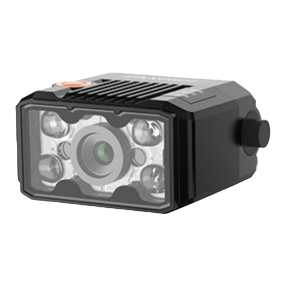
ID2000 Series Smart Code Reader User Manual Chapter 1 Appearance Note Appearance here is for reference only. Refer to the device's specification for detailed dimension information. ● Type I device is a vari focal device that supports adjusting focus manually via its focus knob. This type device has two kinds of data interfaces, including fast Ethernet and USB. - Page 12 ID2000 Series Smart Code Reader User Manual Figure 1-2 Appearance (Type II) Figure 1-3 Appearance (Type III)
- Page 13 ID2000 Series Smart Code Reader User Manual Figure 1-4 Appearance (Type IV) Table 1-1 Component Description Name Description It is used to adjust focal length manually. Focus Knob Note Only type I device has the focus knob. It is used to fix the device to the installation position.
- Page 14 ID2000 Series Smart Code Reader User Manual Name Description It is a network status indicator. The indicator is flashing green when the network transmission is normal. Otherwise, it is unlit. LNK Indicator Note Type IV device does not have a LNK indicator.
-
Page 15: Chapter 2 Connector And Cable
ID2000 Series Smart Code Reader User Manual Chapter 2 Connector and Cable This section introduces the device’s connector on its SR cable and the supplied cable in the package. Note The device’s connector and connector pin definitions may differ by device models. -
Page 16: Type I Device With Fast Ethernet Interface And Type Ii Device
ID2000 Series Smart Code Reader User Manual 2.2 Type I Device with Fast Ethernet Interface and Type II Device Both type I device with fast Ethernet interface and type II device have a 17-pin M12 connector, but their corresponding connector pin definitions are different. Refer to the figure and table below for details. - Page 17 ID2000 Series Smart Code Reader User Manual Signal I/O Signal Source Description Supplied Cable Line 0/1/2/3- Direct current power supply Black open line negative Reserved Reserved Purple open line MDI0- RJ45 Ethernet Fast Ethernet signal MDI0- connector MDI1+ RJ45 Ethernet...
- Page 18 ID2000 Series Smart Code Reader User Manual Signal I/O Signal Source Description Supplied Cable Direct current power supply Black open line negative Reserved Reserved Purple open line MDI0- RJ45 Ethernet Fast Ethernet signal MDI0- connector MDI1+ RJ45 Ethernet Fast Ethernet signal MDI1+...
-
Page 19: Type Iii Device
ID2000 Series Smart Code Reader User Manual 2.3 Type III Device Type III device also has a 17-pin M12 connector. Refer to the figure and table below for connector pin definitions. Figure 2-5 17-Pin M12 Connector Table 2-4 Pin Definitions (Type III Device) - Page 20 ID2000 Series Smart Code Reader User Manual Signal I/O Signal Source Description Supplied Cable Reserved Purple open line MDI0- RJ45 Ethernet Fast Ethernet signal MDI0- connector MDI1+ RJ45 Ethernet Fast Ethernet signal MDI1+ connector GPIO0 Line 0+ It can be configured as input or Gray open line output, and is input by default.
-
Page 21: Type Iv Device With Fast Ethernet Interface
ID2000 Series Smart Code Reader User Manual 2.4 Type IV Device with Fast Ethernet Interface Type IV device with fast Ethernet interface has a DB15 connector. Refer to the figure and table below for connector pin definitions. Figure 2-7 DB15 Connector... - Page 22 ID2000 Series Smart Code Reader User Manual Signal I/O Signal Source Description Supplied Cable RJ45 Ethernet Fast Ethernet signal RX- connector For the type IV device with fast Ethernet interface, you should use the supplied cable, as shown below, to wire the device. The cable has a DB9 female serial port that corresponds to 1st, 2nd, and 3rd pins of the device’s DB15 connector, and a 6-pin terminal that corresponds to 4th, 5th, 8th, 10th,...
-
Page 23: Type Iv Device With Usb Interface
ID2000 Series Smart Code Reader User Manual 2.5 Type IV Device with USB Interface Type IV device with USB interface also has a DB15 connector. Refer to the figure and table below for connector pin definitions. Figure 2-9 DB15 Connector... -
Page 24: Chapter 3 Electrical Feature And I/O Wiring
ID2000 Series Smart Code Reader User Manual Chapter 3 Electrical Feature and I/O Wiring 3.1 Electrical Feature and Wiring of Type I, III and IV Devices ● Type I device has four bi-directional I/O (Line 0/1/2/3). ● Type III device has two bi-directional I/O (Line 0/1), one input (Line 2), and one output (Line 3). -
Page 25: Output Signal
ID2000 Series Smart Code Reader User Manual 3.1.2 Output Signal The internal circuit of the device’s none-isolated output signal is as follows. Figure 3-3 Internal Circuit of Output Signal Internal Logic Output Level High Output Level Low Figure 3-4 Output Logic Level When the external voltage is 12 VDC and pull-up resistor is 1 KΩ, output electric feature is shown... -
Page 26: Bi-Directional Signal
ID2000 Series Smart Code Reader User Manual External Voltage Output Logic Level Low (VL) 12 VDC 500 mV 24 VDC 900 mV 3.1.3 Bi-Directional Signal The type I device has four bi-directional I/O (Line 0/1/2/3) and the type III device has two bi- directional I/O (Line 0/1). - Page 27 ID2000 Series Smart Code Reader User Manual Parameter Name Parameter Symbol Value Input Rising Delay 1 μs Configured as Output Signal Internal Logic Output Level High Output Level Low Figure 3-7 Output Logic Level When the external voltage is 12 VDC and pull-up resistor is 1 KΩ, output electric feature is shown below.
-
Page 28: Input Signal Wiring
ID2000 Series Smart Code Reader User Manual 3.1.4 Input Signal Wiring The device can receive the external input signal via I/O interface, and this section introduces input signal wiring. Note ● Input signal wiring may differ by external device types. - Page 29 ID2000 Series Smart Code Reader User Manual NPN Device If the VCC of NPN device is 12 VDC or 24 VDC, and the pull-up resistor of the supplied 17-pin cable is used. DB9 Connector Internal Resistor NPN Device Power ●...
-
Page 30: Output Signal Wiring
ID2000 Series Smart Code Reader User Manual 3.1.5 Output Signal Wiring Note ● Output signal wiring may differ by external device types. ● The supplied 17-pin cable of type I and type III has pull-up and pull-down resistors, and type IV device’s supplied cable does not have pull-up and pull-down resistors. -
Page 31: Electrical Feature And Wiring Of Type Ii Device
ID2000 Series Smart Code Reader User Manual recommended to use 1 KΩ pull-up resistor. NPN Device Power DB9 Connector ● None-isolated ● Signal Line Output Device NPN Power Ground Output Signal Ground GND of VCC GND of PWR Figure 3-15 Output Signal Connecting to NPN Device (External Pull-Up Resistor Used) 3.2 Electrical Feature and Wiring of Type II Device... -
Page 32: Output Signal
ID2000 Series Smart Code Reader User Manual Input Level High Input Level Low Internal Logic Figure 3-17 Input Logic Level Table 3-7 Input Electrical Feature Parameter Name Parameter Symbol Value Input Logic Level Low 1.5 VDC Input Logic Level High... -
Page 33: Input Signal Wiring
ID2000 Series Smart Code Reader User Manual Internal Logic Output Level High Output Level Low Figure 3-19 Output Logic Level Table 3-8 Output Electrical Feature Parameter Name Parameter Symbol Value Output Logic Level Low 730 mV Output Logic Level High 3.2 VDC... -
Page 34: Output Signal Wiring
ID2000 Series Smart Code Reader User Manual PNP Device PNP Device Power DB9 Connector Opto Input Signal Line Device Input Signal Ground PNP Power Ground GND of VCC GND of PWR Figure 3-20 Input Signal Connecting to PNP Device NPN Device If the VCC of NPN device is 12 VDC or 24 VDC, and the pull-up resistor of the supplied 17-pin cable is used. - Page 35 ID2000 Series Smart Code Reader User Manual output signal wiring. Note ● Output signal wiring may differ by external device types. ● The supplied 17-pin cable has pull-up and pull-down resistors. ● The voltage of VCC should be equal to or less than that of PWR. Otherwise, the output signal exception may occur.
-
Page 36: Serial Port
ID2000 Series Smart Code Reader User Manual recommended to use 1 KΩ pull-up resistor. NPN Device Power DB9 Connector ● Opto Output ● Signal Line Device NPN Power Ground Output Signal Ground GND of VCC GND of PWR Figure 3-25 Output Signal Connecting to NPN Device (External Pull-Up Resistor Used) 3.3 RS-232 Serial Port... -
Page 37: Chapter 4 Installation
ID2000 Series Smart Code Reader User Manual Chapter 4 Installation 4.1 Installation Preparation You need to prepare following accessories before installation. Table 4-1 Accessories Name Quantity Description It refers to the supplied cable that is included in the package. Cable Refer to section Connector and Cable for details. - Page 38 ID2000 Series Smart Code Reader User Manual ● For type IV device with fast Ethernet interface, connect the device to the supplied cable via the DB15 connector, insert RJ45 connector of the cable into a switch or a PC for debugging images or transmitting data, and connect the device to a power adapter or a switch power supply for power supply.
-
Page 39: Chapter 5 Device Connection
ID2000 Series Smart Code Reader User Manual Chapter 5 Device Connection Device connection to the client software is required for device’s configuration and remote operations. This section introduces how to install the client software, set PC environment, connect the device to the client software, etc. -
Page 40: Set Pc Environment
ID2000 Series Smart Code Reader User Manual 5.2 Set PC Environment To ensure stable client running and data transmission, you are recommended to set PC environment. For the network device, you need to turn off the firewall and set PC network. For the USB device, you need to check the USB drive on the PC. -
Page 41: Check Usb Drive For Usb Device
ID2000 Series Smart Code Reader User Manual 1. Go to PC network settings page: Start → Control Panel → Network and Internet → Network and Sharing Center → Change adapter settings. 2. Select NIC and set the IP obtainment mode. -
Page 42: Set Device Network
ID2000 Series Smart Code Reader User Manual 5.3 Set Device Network You can set and operate the device in the client software only when the device is in the same network segment with the PC where the client software is installed. -
Page 43: Chapter 6 Client Software Layout
ID2000 Series Smart Code Reader User Manual Chapter 6 Client Software Layout After connecting to the device, the client software can read the device information and display it. Figure 6-1 Main Window Note The specific interfaces of the client software may differ by its versions. - Page 44 ID2000 Series Smart Code Reader User Manual You can set device parameters in device configuration area. Figure 6-2 Device Configuration Area Table 6-2 Configuration Area Description Module Name Description You can connect or disconnect device, modify device IP Device Connection address, view device information, etc.
-
Page 45: Chapter 7 Device Mode Settings
ID2000 Series Smart Code Reader User Manual Chapter 7 Device Mode Settings The device supports 3 types of operating modes, including Test, Normal, and Raw. You can select different modes in live view window according to actual demands. Note ● Stopping the real-time acquisition is required before selecting modes. -
Page 46: Chapter 8 Device Settings
ID2000 Series Smart Code Reader User Manual Chapter 8 Device Settings You are recommended to complete device settings in following order: Device Connection → Image Settings → Algorithm Settings → I/O Control Settings → Data Processing → Communication Settings → Configuration Management. - Page 47 ID2000 Series Smart Code Reader User Manual parameters. ● For specific parameter range like exposure time, gain and acquisition frame rate, refer to the device's specification for details. Exposure Time You can increase exposure time to improve image brightness. Note To some extent, increasing exposure time will reduce acquisition frame rate, and impact image quality.
-
Page 48: Set Polling
ID2000 Series Smart Code Reader User Manual Figure 8-1 Set Image 8.1.2 Set Polling The polling function allows the device to acquire images based on the parameters you set, including exposure time, gain, Gamma, light source, focus position, etc. Currently, 2 types of polling modes are available, including single mode and multiple mode. - Page 49 ID2000 Series Smart Code Reader User Manual Figure 8-2 Single Mode Multiple Mode Note ● In multiple mode, the device supports trigger parameters like software trigger, external trigger, TCP, etc., does not support stopping polling via the external trigger. ● The parameter of Best Polling Group Idx is used to display the polling parameter number when the device recognizes codes after enabling polling.
-
Page 50: Set Light Source
ID2000 Series Smart Code Reader User Manual 8. Repeat step 4 to step 7 to set other parameters from Polling Param. Figure 8-3 Multiple Mode Parameter 1 Parameter 4 Parameter 2 Parameter 3 Exposure Time 1 Exposure Time 4 Exposure Time 3... -
Page 51: Set Lens Focus
ID2000 Series Smart Code Reader User Manual related parameters according to actual demands. Note ● Light source parameters may differ by device models. ● Make sure you have selected the device to be set in Device Connection before setting light source parameters. - Page 52 ID2000 Series Smart Code Reader User Manual 2. Right click the device in Device Connection, and click Feature Tree. 3. Go to Focus Control → Auto Config, and select the focus mode according to actual demands. ● Full Auto: In this mode, the device will automatically change parameters like focus position, exposure, gain, Gamma and light source when adjusting focus.
- Page 53 ID2000 Series Smart Code Reader User Manual Figure 8-7 Manual Focus 5. Observe image clarity in the live view widow, and click in Adjust Focus to adjust focus according to actual demands. 6. (Optional) Select the position parameter from Focus Position, and click Execute in Focus Position Save to save the focus position after adjusting focus.
- Page 54 ID2000 Series Smart Code Reader User Manual Figure 8-8 Adjust Focus via External Devices 4. (Optional) Set TCP Focus Port if TCP is selected as Focus Label Source. Figure 8-9 Set TCP Focus Port 5. (Optional) Set UDP Focus Port if UDP is selected as Focus Label Source.
-
Page 55: Set Self-Adaptive Adjustment
ID2000 Series Smart Code Reader User Manual 6. (Optional) Set Serial Baudrate, Serial Data Bits, Serial Parity, and Serial Stop Bits if Serial is selected as Focus Label Source. Figure 8-11 Serial Related Parameters 7. Enable Focus Label Valid after settings, and external devices can control the device to adjust focus via sending trigger commands. -
Page 56: Set Mirror X
ID2000 Series Smart Code Reader User Manual ● Default Param: It adjusts the default parameters. ● Polling Param: It adjusts parameters configured in polling. After Polling Param is selected as Param Source, you can select polling parameter group from Polling Param, and enable Apply Polling Focus to adjust polling focus according to actual demands. -
Page 57: Set Test Pattern
ID2000 Series Smart Code Reader User Manual Go to Image Settings, click All Features to display other features, and set Mirror X according to actual demands. Note This function is enabled by default, and it may differ by device models. -
Page 58: Set Code Reading Roi
ID2000 Series Smart Code Reader User Manual Figure 8-13 Add Codes 8.2.2 Set Code Reading ROI Algorithm ROI (Region of Interest) allows the device to execute algorithms and read codes on the specific area you selected, and thus improving code reading efficiency. - Page 59 ID2000 Series Smart Code Reader User Manual Draw Single Group of ROI Steps 1. Go to Algorithm Settings, click All Features, and find Algorithm ROI. 2. Click Draw to draw ROI in the live view window. 3. (Optional) Repeat the above step to draw multiple ROIs according to actual demands.
- Page 60 ID2000 Series Smart Code Reader User Manual Draw ROI in Batch Steps 1. Go to Algorithm Settings, click All Features, and find Algorithm ROI. 2. Click Batch to set parameters according to actual demands. ● Area Offset: It sets the pixel quantity from the starting point when the ROI is in horizontal and vertical direction from the full resolution.
- Page 61 ID2000 Series Smart Code Reader User Manual Figure 8-16 Create Chessboard ROI 3. Click after creating ROI, and the red frame becomes green as shown below. Figure 8-17 Draw ROI via Chessboard 4. (Optional) Click to restore the ROI to the full screen, and click to clean all configured ROIs.
-
Page 62: Set 1D Algorithm Parameter
ID2000 Series Smart Code Reader User Manual 8.2.3 Set 1D Algorithm Parameter Click All Features on the upper-right to display all algorithm parameters. In the Algorithm Parameter page, select 1DCode as Arithmetic Type, and then you can set its corresponding parameters. - Page 63 ID2000 Series Smart Code Reader User Manual parameters. Note ● You should have selected at least one type of 2D code. ● For different models of the device, the specific parameters may differ, and the actual device you purchased shall prevail.
- Page 64 ID2000 Series Smart Code Reader User Manual Figure 8-18 White QR Code Figure 8-19 Black QR Code ● For DM code, the code color is determined by the color of its "L" shaped sides. White "L" shaped sides indicate that the code color is white, and black "L" shaped sides indicate that the code color is black.
-
Page 65: Set 2D Code Quality Evaluation
ID2000 Series Smart Code Reader User Manual continuous. Usually the continuous code uses squares as the minimum units. Discrete stands for the minimum units in the "L" shaped sides of the DM code are discrete, or the minimum units in the concentric square like in the QR code are discrete. -
Page 66: Set Code Score
ID2000 Series Smart Code Reader User Manual Steps 1. Set Sym Proc Type according to actual demands, and the default type is Type 1. Type 1 has a strong capacity to locate codes. 2. Set Iso Edition, including Iso15415 and Iso29158 ●... -
Page 67: Line Mode Settings
ID2000 Series Smart Code Reader User Manual ● The code score is determined by two factors including image quality and print quality of codes. The range of code score is between 0 and 100, and the higher the score, and easier the code can be read. -
Page 68: Signal Input Settings
ID2000 Series Smart Code Reader User Manual output by default. ● Line 0 should be same with Line 1 as input or output, and Line 2 should be same with Line 3 as input or output. Figure 8-25 Set Line Mode 8.4 Signal Input Settings... -
Page 69: Enable External Trigger Mode
ID2000 Series Smart Code Reader User Manual 8.4.3 Enable External Trigger Mode In the external trigger mode, the device acquires images via external signals like software signal and hardware signal. You have 2 methods to enable the external trigger mode: ●... - Page 70 ID2000 Series Smart Code Reader User Manual Note ● When selecting Rising Edge or Falling Edge as Line Out Trigger In Polarity, you can set Trigger Delay. ● When selecting Level High or Level Low as Line Out Trigger In Polarity, you can set Start Delay Time and End Delay Time according to actual demands.
- Page 71 ID2000 Series Smart Code Reader User Manual Set and Execute TCP Trigger Mode TCP start specifies the TCP server as the source for the trigger signal. When the server receives the specified string text, the trigger signal will be outputted.
- Page 72 ID2000 Series Smart Code Reader User Manual Set and Execute Serial Port Trigger Mode Serial start specifies the serial port as the source for the trigger signal. When the serial port receives the specified string text, the trigger signal will be outputted.
-
Page 73: Stop Trigger
ID2000 Series Smart Code Reader User Manual Note You need to go to Feature Tree, find Trigger IO Control, and set USB Start as Trigger Source. 8.4.4 Stop Trigger The device supports stopping trigger via TCP, UDP, I/O, serial port and USB. You can also set code reading timeout duration or max. - Page 74 ID2000 Series Smart Code Reader User Manual Figure 8-34 Stop Trigger via UDP Stop Trigger via IO You can stop a trigger via IO: Enabling IO Stop Trigger Enable first, select specific sources from IO Stop Trigger Selector, and then set the trigger polarity as the condition to stop trigger.
- Page 75 ID2000 Series Smart Code Reader User Manual Figure 8-36 Software Trigger End Stop Trigger via Serial Port When the specified serial port receives the specified string text, the trigger will be stopped. Click I/O Control Settings → Stop Trigger, enable Serial Stop Trigger Enable, set Serial Stop Trigger Text, Serial Baud Rate, Serial Data Bits, Serial parity, and Serial Stop Bits according to actual demands.
- Page 76 ID2000 Series Smart Code Reader User Manual Go to Feature Tree, find Stop Trigger Control, enable USB Stop Trigger Enable, set USB Stop Trigger Text, USB Baudrate, USB Data Bits, USB Parity, and USB Stop Bits according to actual demands.
-
Page 77: Signal Output Settings
ID2000 Series Smart Code Reader User Manual Trigger Min and CodeNum Stop Trigger Max according to actual demands. ● If the outputted code quantity is smaller than configured CodeNum Stop Trigger Min, and the device will output codes continuously. ● If the outputted code quantity is smaller than configured CodeNum Stop Trigger Max, and the device will stop outputting codes. -
Page 78: Enable Line Inverter
ID2000 Series Smart Code Reader User Manual 8.5.2 Enable Line Inverter The line inverter function allows the device to invert the electrical signal level of an I/O line, and meets requirements of different devices for high or low electrical signal level. - Page 79 ID2000 Series Smart Code Reader User Manual Select No Code Read If you select NoCodeRead as Line Out Activation Event, you can set its output delay time and duration. Line Out Delay Time It sets the delay time for outputting the output signal.
-
Page 80: Set Buzzer
ID2000 Series Smart Code Reader User Manual Figure 8-45 Select Read Success 8.5.4 Set Buzzer Note ● Only type IV device supports buzzer function. ● Make sure that the device is the Normal mode before using the buzzer function. The buzzer is used to indicate the device’s operation status, and you can set the buzzer function according to actual demands. -
Page 81: Code Reading Result Settings
ID2000 Series Smart Code Reader User Manual 8.6 Code Reading Result Settings In Data Processing module, you can set filter rules for reading codes and other data processing related parameters. 8.6.1 Set Code Reading Result Output Mode There are 2 types of output modes when the device mode is Normal and trigger mode is On: Instant output mode and non-instant output mode. - Page 82 ID2000 Series Smart Code Reader User Manual Max. Output Length It sets the max. length of code that can be output. Code Offset Num It sets the range of code to be filtered. For example, the code is ABCDEFG, if you set this parameter as 2, the device will output CDEFG at last and filter AB.
-
Page 83: Set Result Format
ID2000 Series Smart Code Reader User Manual Figure 8-47 Set Filter Rule 8.6.3 Set Result Format Result format settings allow you to set the format and contents contained in the outputted code information. Result format is related to communication protocol and trigger mode. With different selected communication protocol and trigger mode, you need to set corresponding parameters. - Page 84 ID2000 Series Smart Code Reader User Manual Note The configurable parameters may differ if the internal trigger mode is enabled. NoRead Image Index It sets the specific image that is outputted when no code information is read. For example, if you set this parameter as 5, and the 5th image will be output.
- Page 85 ID2000 Series Smart Code Reader User Manual If it is enabled, and the device will output the content you set in TCP Output NoRead Text when no code is recognized. TCP Output Start Text The contents of the start part of the data outputted. You can set the contents according to actual condition.
- Page 86 ID2000 Series Smart Code Reader User Manual NoRead Image Index It sets the specific image that is outputted when no code information is read. For example, if you set this parameter as 5, and the 5th image will be output.
- Page 87 ID2000 Series Smart Code Reader User Manual FTP File Name Contain FTP Timestamp Type If this parameter is enabled, you can select different types of timestamp. Figure 8-50 Result Output via FTP Result Output via USB, UDP or SLMP If USB, UDP or SLMP is selected as Communication Protocols, you need to set following parameters.
-
Page 88: Communication Settings
ID2000 Series Smart Code Reader User Manual you set this parameter as 5, and the 5th image will be output. UDP Format Check You should click Execute in UDP Format Check to check if you entered is right in format, and the check result will be displayed in UDP Format Check Result. -
Page 89: Smart Sdk
ID2000 Series Smart Code Reader User Manual communication protocol is related to the device modes. With various device modes, the device supports different communication protocols and corresponding parameters. When the camera mode is Test or Raw, the device only supports SmartSDK protocol and no parameter settings are required. -
Page 90: Serial
ID2000 Series Smart Code Reader User Manual Figure 8-53 TCP Client 8.7.3 Serial If Serial is selected as the Communication Protocols, you can enable Serial Protocol, enter Serial Baud Rate, Serial Data Bits, Serial Parity, and Serial Stop Bits. Figure 8-54 Serial 8.7.4 FTP... -
Page 91: Http
ID2000 Series Smart Code Reader User Manual Figure 8-55 FTP 8.7.5 HTTP If select HTTP as the Communication Protocols, you can enable HTTP Server, enter HTTP Sever Port and WebRefresh Cycle. HTTP Server If enabled, the device will output data via HTTP server. -
Page 92: Profinet
ID2000 Series Smart Code Reader User Manual enter TCP Server Port. Figure 8-57 TCP Server 8.7.7 Profinet If Profinet is selected as the Communication Protocols, you can enable Profinet Enable and set Profinet Device Name, Profinet Result Module Size, and Profinet Result Timeout (s) according to actual demands. - Page 93 ID2000 Series Smart Code Reader User Manual It sets the network number of MELSEC. MELSEC Node Number It sets the node number of MELSEC. MELSEC Processor Number It sets processor number. MELSEC Control Poll Interval (ms) It sets how often read data of the control area.
-
Page 94: Ethernet/Ip
ID2000 Series Smart Code Reader User Manual Figure 8-59 MELSEC 8.7.9 Ethernet/IP If Ethernet/IP is selected as the Communication Protocols, you can enable Ethernet/IP Enable, and the device will output data via Ethernet/IP. You can set Ethernet/IP Input Assembly Size (Word), Ethernet/IP Output Assembly Size (Word), Ethernet/IP Result Byte Swap, and Ethernet/IP Result Timeout (s) according to actual demands. -
Page 95: Modbus
ID2000 Series Smart Code Reader User Manual Figure 8-60 Ethernet/IP 8.7.10 ModBus If ModBus is selected as the Communication Protocols, you can enable ModBus Enable and set related parameters according to actual demands. ModBus Mode It includes server and client, and is server by default. -
Page 96: Udp
ID2000 Series Smart Code Reader User Manual ModBus Result Size (Word) It sets max. length of ModBus result. It is 100 by default. ModBus Result Byte Swap If it is enabled, the client software will swap ModBus results. ModBus Result Timeout (s) It sets the ModBus result timeout, and the unit is s. -
Page 97: Fins
ID2000 Series Smart Code Reader User Manual Figure 8-62 UDP 8.7.12 Fins If Fins is selected as the Communication Protocols, you can enable Fins Enable and set related parameters according to actual demands. Fins Server IP It sets the server IP of Fins. -
Page 98: Usb
ID2000 Series Smart Code Reader User Manual It sets the start offset address of the result area. Fins Result Size (Word) It sets the size of the result area. Fins Result Byte Swap If it is enabled, the client software will swap Fins results. - Page 99 ID2000 Series Smart Code Reader User Manual Figure 8-64 USB Some device models support setting USB communication parameters via reading setting codes. You need to let the device read the code of starting settings to enable the function, and read the code of ending settings to disable the function.
-
Page 100: Set Multicast
ID2000 Series Smart Code Reader User Manual Table 8-1 USB Setting Codes Setting Codes Function Setting Codes Function Enable USB HID Enable USB CDC communication communication mode mode 8.8 Set Multicast The multicast function is used to let multiple devices have the same trigger number when they are acquiring images and analyzing codes at the same time. -
Page 101: User Set Customization
ID2000 Series Smart Code Reader User Manual 3. Set GroupID. Note You should set the same GroupID for devices in the same multicast system. 4. (Optional) After automatic networking, you can view the main device’s name, IP address, and serial number via MultiCameraInfo, and view sub devices’ name, IP address, and serial number via SubCameraInfo. -
Page 102: Chapter 9 Device Operation
ID2000 Series Smart Code Reader User Manual Chapter 9 Device Operation The device operation section introduces some basic device operations about how to start live view, acquisition and recording, add cross line in the image, split window, view reports, etc. -
Page 103: Add Cross Line
ID2000 Series Smart Code Reader User Manual Figure 9-2 Enable Acquisition 9.3 Add Cross Line During live view, you can add a cross line on the live view image to adjust the position of the object in the view. Click... -
Page 104: Split Window
ID2000 Series Smart Code Reader User Manual Figure 9-4 Start Recording 9.5 Split Window The client software supports window division function that allows you to split the window into multiple-window mode to view the live view of multiple devices at the same time. -
Page 105: View Log
ID2000 Series Smart Code Reader User Manual Figure 9-6 View Reports 9.7 View Log You can view the device logs and export them to the local PC. Click in control toolbar to open the device log window, and you can view different types of logs, including device errors, warning, and informational log, etc. -
Page 106: Enable Device Auto Work
ID2000 Series Smart Code Reader User Manual Figure 9-8 Set NTP Timing 9.9 Enable Device Auto Work This function allows the device to automatically enter the operating status after being powered You can go to Config Management → Device Auto Work Enable, and enable Device Auto Work Enable. -
Page 107: Chapter 10 Device Maintenance
ID2000 Series Smart Code Reader User Manual Chapter 10 Device Maintenance 10.1 Update Firmware The device supports updating firmware via the client software. Note ● Disconnect the device with client software. ● Please use the firmware package of the corresponding device model for upgrading. - Page 108 ID2000 Series Smart Code Reader User Manual Figure 10-2 Reboot Device...
-
Page 109: Chapter 11 Faq (Frequently Asked Question)
ID2000 Series Smart Code Reader User Manual Chapter 11 FAQ (Frequently Asked Question) 11.1 Why the image is very dark? Problem All black or too dark during preview. Reason Too small adjustment value of exposure and gain. Solution Increase exposure and gain appropriately. -
Page 110: Why There Is No Image In The Live View
ID2000 Series Smart Code Reader User Manual make sure that the device is powered up normally. ● Check the network connection (observe whether the LNK light is flashing green or not) to make sure the device can be connected to the network normally, and the PC network and the device are in the same network segment. - Page 111 UD26354B...
Need help?
Do you have a question about the ID2000 Series and is the answer not in the manual?
Questions and answers