Table of Contents
Advertisement
Available languages
Available languages
Advertisement
Table of Contents

Related Manuals for FS S5300-12S


Summary of Contents for FS S5300-12S
- Page 1 8 12 S5300 -12S CON SOL E PW R S5300-12S ETHERNET SWITCH ETHERNET-SWITCH SWITCH ETHERNET イーサネットスイッチ Quick Start Guide V1.0 Quick Start Anleitung Guide de Démarrage Rapide クイックスタートガイド...
- Page 2 Introduction Thank you for choosing the S5300-12S Switch. This guide is designed to familiarize you with the layout of the switch and describes how to deploy it in your network. CONSOLE S5300-12S S5300-12S Accessories Power Cord x2 Console Cable x1...
-
Page 3: Hardware Overview
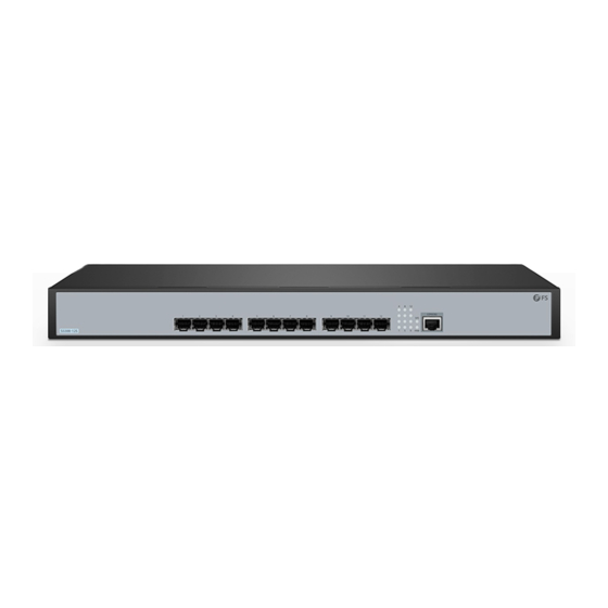
This power cord cannot be used with other devices, and other power cords should not be used with this device. Hardware Overview Front Panel LEDs Link/ACT CONSOLE S5300-12S Description LEDs State Blinking Green The system is operating normally. Solid Green The device is powered on. -
Page 4: Installation Requirements
Description Ports SFP+ SFP+ ports for 10G connection CONSOLE An RJ45 console port for serial management Installation Requirements Before the installation, make sure that you have the following conditions ready: Phillips screwdriver, related bolts and ESD tools. Standard-sized, 19" wide rack with a minimum of 1U height available. Fiber optic cables and ber transceivers. -
Page 5: Mounting The Switch
Mounting the Switch Desk Mounting S5300 -12S CONSO LE IES5 100- 24FS 1. Attach four rubber pads to the bottom of the switch. 2. Place the switch on a stable desk. NOTE: Do not place heavy objects on the switch. Rack Mounting CO N SO SY S... -
Page 6: Grounding The Switch
S5 30 0- 12 CO NS OL SY S PW R 2. Install the switch on the rack with screws and cage nuts. Grounding the Switch P O W E R In p u t: 1 0 0 -2 4 0 V a c F re q : 5 0 /6 0 H z... -
Page 7: Connecting The Console Port
Connecting the SFP+ Ports S5 30 0- 12 CO N SO SY S PW R 1. Plug the compatible SFP+ transceiver into the SFP+ port. 2. Connect a ber optic cable to the ber transceiver. Then connect the other end of the cable to another ber device. -
Page 8: Connecting The Power
Connecting the Power P O W E R In p u t: 1 0 0 -2 4 0 V a c F re q : 5 0 /6 0 H z 1. Plug the AC power cord into the power port on the back panel of the switch. 2. - Page 9 I nter n et Proto col Versi on 4 ( TCP/ IP v4) Prope r t ie s General Yo u c a n g e t I P s e t t i n g s a s s i g n e d a u t o m a t i c a l l y i f y o u r n e t w o r k s u p p o r t s t h i s c a p a b i l i t y.
-
Page 10: Troubleshooting
Con guring the Switch Using the Console Port Step 1: Connect a computer to the console port of the switch with the console cable. Step 2: Start the terminal simulation software, such as HyperTerminal on the computer. Step 3: Set the parameters of the HyperTerminal: Baud rate to 115200, Data bits to 8, Parity to None, and Stop bits to 1. -
Page 11: Online Resources
Product Warranty FS ensures our customers that for any damage or faulty items due to our workmanship, we will o er a free return within 30 days from the day you receive your goods. This excludes any custom-made items or tailored solutions. - Page 12 Einführung Vielen Dank, dass Sie sich für den S5300-12S Switch entschieden haben. Diese Anleitung soll Sie mit dem Aufbau des Switches vertraut machen und beschreibt, wie Sie ihn in Ihrem Netzwerk einsetzen können. CONSOLE S5300-12S S5300-12S Zubehör Netzkabel x2 Console-Kabel x1...
- Page 13 HINWEIS: Dieses Netzkabel kann nicht mit anderen Geräten verwendet werden, und andere Netzkabel sollten nicht mit diesem Gerät verwendet werden. Hardware-Übersicht LEDs an der Vorderseite Link/ACT CONSOLE S5300-12S Beschreibung LEDs Status Blinkt Grün Das System funktioniert ordnungsgemäß. Durchgehend Grün Das Gerät ist eingeschaltet.
- Page 14 Beschreibung Ports SFP+ SFP+-Ports für 10G-Verbindung CONSOLE Ein RJ45-Console-Port für die serielle Verwaltung Installationsvoraussetzungen Vergewissern Sie sich vor der Installation, dass Sie die folgenden Voraussetzungen erfüllen: Kreuzschlitzschraubendreher, entsprechende Schrauben und ESD-Werkzeuge. Ein 19"-Rack in Standardgröße mit einer Mindesthöhe von 1 HE. Glasfaserkabel und Glasfasertransceiver.
-
Page 15: Montage Des Switches
Montage des Switches Tischmontage S5300 -12S CONSO LE IES5 100- 24FS 1. Befestigen Sie vier Gummipads an der Unterseite des Switches. 2. Stellen Sie den Switch auf einen stabilen Tisch. HINWEIS: Stellen Sie keine schweren Gegenstände auf den Switch. Rack-Montage CO N SO SY S PW R... - Page 16 S5 30 0- 12 CO NS OL SY S PW R 2. Montieren Sie den Switch mit Schrauben und Kä gmuttern am Rack. Erdung des Switches P O W E R In p u t: 1 0 0 -2 4 0 V a c F re q : 5 0 /6 0 H z...
- Page 17 Anschließen der SFP+ Ports S5 30 0- 12 CO N SO SY S PW R 1. Stecken Sie den kompatiblen SFP+-Transceiver in den SFP+-Port. 2. Schließen Sie ein Glasfaserkabel an den Glasfaser-Transceiver an. Schließen Sie dann das andere Ende des Kabels an ein anderes Glasfasergerät an. Anschließen des Console-Ports S5 30 0- 12 CO NS OL...
-
Page 18: Anschließen Der Stromversorgung
Anschließen der Stromversorgung P O W E R In p u t: 1 0 0 -2 4 0 V a c F re q : 5 0 /6 0 H z 1. Stecken Sie das Netzkabel in den Netzanschluss auf der Rückseite des Switches. 2. - Page 19 I nter n et Proto col Versi on 4 ( TCP/ IP v4) Prope r t ie s General Yo u c a n g e t I P s e t t i n g s a s s i g n e d a u t o m a t i c a l l y i f y o u r n e t w o r k s u p p o r t s t h i s c a p a b i l i t y.
-
Page 20: Fehlerbehebung
Kon guration des Switches über den Console-Port Schritt 1: Schließen Sie einen Computer über das Console-Kabel an den Console-Port des Switches an. Schritt 2: Starten Sie die Terminalsimulationssoftware, z. B. HyperTerminal, auf dem Computer. Schritt 3: Stellen Sie die Parameter von HyperTerminal ein: Baudrate auf 115200, Datenbits auf 8, Parität auf Keine und Stoppbits auf 1. - Page 21 Produktgarantie FS garantiert seinen Kunden, dass wir im Falle von Schäden oder fehlerhaften Artikeln, die auf unsere Verarbeitung zurückzuführen sind, eine kostenlose Rückgabe innerhalb von 30 Tagen ab dem Tag des Erhalts der Ware anbieten. Dies gilt nicht für Sonderanfertigungen oder maßgeschneiderte Lösungen.
- Page 22 Introduction Merci d'avoir choisi le switch S5300-12S. Ce guide est conçu pour vous familiariser avec la con guration du commutateur et décrit comment procéder à son déploiement. CONSOLE S5300-12S S5300-12S Accessoires Câble d'Alimentation x2 Câble de Console x1 Câble Ethernet x1 Câble de Mise à...
-
Page 23: Aperçu Du Matériel
Ce cordon d'alimentation ne peut pas être utilisé avec d'autres appareils, et les autres cordons d'alimentation ne doivent pas être utilisés avec cet appareil. Aperçu du Matériel LED du Panneau Frontal Link/ACT CONSOLE S5300-12S Description Statut Vert Clignotant Le système fonctionne normalement. Vert L'appareil est sous tension. -
Page 24: Conditions D'installation
Description Ports SFP+ Ports SFP+ pour connexion 10G CONSOLE Un port console RJ45 pour la gestion en série Conditions d'Installation Avant l'installation, assurez-vous que vous disposez des éléments suivants : Tournevis Phillips, boulons et outils ESD. Un rack standard de 19" de large avec un minimum de 1U de hauteur disponible. Câbles à... -
Page 25: Installation En Rack
Installation du Switch Installation sur Bureau ou Support S5300 -12S CONSO LE IES5 100- 24FS 1. Fixez quatre pads en caoutchouc à la base du switch. 2. Placez le switch sur un bureau ou surface stable. NOTE : Ne pas placer d'objets lourds sur le switch. Installation en Rack CO N SO SY S... - Page 26 S5 30 0- 12 CO NS OL SY S PW R 2. Installez le switch dans le rack à l'aide de vis et d'écrous à cage. Mise à la Terre du Switch P O W E R In p u t: 1 0 0 -2 4 0 V a c F re q : 5 0...
- Page 27 Connexion des Ports SFP+ S5 30 0- 12 CO N SO SY S PW R 1. Branchez l'émetteur-récepteur SFP+ compatible dans le port SFP+. 2. Connectez un câble à bre optique à l'émetteur-récepteur à bre optique. Connectez ensuite l'autre extrémité du câble à un autre dispositif à bre optique. Connexion du Port de Console S5 30 0- 12 CO NS OL...
-
Page 28: Connexion De L'alimentation
Connexion de l'Alimentation P O W E R In p u t: 1 0 0 -2 4 0 V a c F re q : 5 0 /6 0 H z 1. Branchez le câble d'alimentation AC dans le port d'alimentation situé sur le panneau arrière du switch. - Page 29 I nter n et Proto col Versi on 4 ( TCP/ IP v4) Prope r t ie s General Yo u c a n g e t I P s e t t i n g s a s s i g n e d a u t o m a t i c a l l y i f y o u r n e t w o r k s u p p o r t s t h i s c a p a b i l i t y.
-
Page 30: Dépannage
Con guration du Switch à l'Aide du Port Console Étape 1 : Connectez un ordinateur au port de console du switch à l'aide du câble de console. Étape 2 : Lancez le logiciel HyperTerminal sur l'ordinateur. Étape 3 : Dé nissez les paramètres de l'HyperTerminal : 115200 pour le Débit en bauds, 8 pour les Bits de données, None pour la Parité... -
Page 31: Garantie Du Produit
Garantie du Produit FS garantit à ses clients que tout article endommagé ou défectueux en raison de sa fabrication pourra être retourné gratuitement dans un délai de 30 jours à compter de la date de réception de la marchandise. Cette garantie ne s'applique pas aux articles fabriqués sur mesure ou aux solutions personnalisées. - Page 32 イントロダクション S����-��Sスイッチをお選びいただきありがとうございます。このガイドは、スイッチのレ イアウトに慣れることを目的としており、ネットワークにスイッチを導入する方法について 説明します。 CONSOLE S5300-12S S5300-12S アクセサリー 電源コード x� コンソールケーブル x� イーサネッ トケーブル x� 接地ケーブル x� M�ネジ x� M�ケージナット x� M�ネジ x� ラバーパッド x� 取り付けブラケット x�...
- Page 33 注: アクセサリーはイラストと異なる場合がありますので、現物をご了承ください。 注: この電源コードは他の機器には使用できません。また、他の電源コードはこの 機器に使用しないでください。 ハードウェア概要 フロントパネルLED Link/ACT CONSOLE S5300-12S 説明 状態 緑色点滅 システムは正常に動作しています。 緑色点灯 デバイスの電源が入っています。 点滅 ポートはトラフィックを送受信しています。 Link/ACT フロントパネルポート SFP+ CONSOLE S5300-12S コンソール...
- Page 34 説明 ポート ��G接続用SFP+ポート SFP+ コンソール シリアル管理用RJ��コンソールポート 設置要件 インストールする前に、次の条件が整っていることを確認してください: プラスドライバー、関連ボルト、ESDツール。 標準サイズの��インチ幅のラックで、�U以上の高さが利用できます。 光ファイバケーブル、光ファイバトランシーバー。 サイト環境 動作温度範囲は�℃~��℃に保ってください。 動作湿度が�% ~ ��%に維持されていることを確認してください。 設置場所には、水漏れ、水滴、多露、湿気がないことが必要です。 設置場所は埃のない状態に保ってください。 設置場所は換気が十分である必要があります。スイッチの周囲に適切な空気の流れがあ ることを確認してください。 危険な状態を避けるために、スイッチが水平で安定していることを確認してください。 ラックと作業台が、スイッチとその付属品の設置重量を支えるのに十分な固さであること を確認してください。 ラックと作業台が適切に接地されていることを確認してください。 デバイスのエンクロージャーを分解しないでください。 デバイスを清掃する前に電源を切ってください。デバイスを拭くために液体を使用しない でください。 S5 30 0- 12 デバイスを電気力線、ランプ、送電網から遠ざけてください。...
- Page 35 スイッチの取り付け デスクへの取り付け S5300 -12S CONSO LE IES5 100- 24FS �. スイッチの底面に�つのゴムパッドを取り付けます。 �. スイッチを安定した机の上に置きます。 注: スイッチの上に重いものを置かないでください。 ラック取り付け CO N SO SY S PW R �. 取り付けブラケットをスイッチの両側面にネジで固定します。...
- Page 36 S5 30 0- 12 CO NS OL SY S PW R �. ネジとケージナットを使用してスイッチをラックに取り付けます。 スイッチの接地 P O W E R In p u t: 1 0 0 -2 4 0 V a c F re q : 5 0 /6 0 H z �.
- Page 37 SFP+ポートの接続 S5 30 0- 12 CO N SO SY S PW R �. 互換性のあるSFP+トランシーバーをSFP+ポートに接続します。 �. 光ファイバケーブルをファイバトランシーバーに接続します。次に、ケーブルのもう一方 の端を別のファイバデバイスに接続します。 コンソールポートの接続 S5 30 0- 12 CO NS OL SY S PW R �. RJ��コネクタをスイッチのRJ��コンソールポートに挿入します。 �. コンソールケーブルのDB�メスコネクタを、コンピュータのシリアルポートに接続します。...
- Page 38 電源の接続 P O W E R In p u t: 1 0 0 -2 4 0 V a c F re q : 5 0 /6 0 H z �. AC電源コードをスイッチのバックパネルにある電源ポートに差し込みます。 �. 電源コードのもう一方の端をAC電源に接続します。 警告: 電源が入っているときは、電源コードを取り付けないでください。 スイッチの設定 Webベースのインターフェイスを使用してスイッチを設定する ステップ�: ネットワーク ケーブルを使用して、コンピュータをスイッチのイーサネットポー トに接続します。...
- Page 39 I nter n et Proto col Versi on 4 ( TCP/ IP v4) Prope r t ie s General Yo u c a n g e t I P s e t t i n g s a s s i g n e d a u t o m a t i c a l l y i f y o u r n e t w o r k s u p p o r t s t h i s c a p a b i l i t y.
- Page 40 コンソールポートを使用してスイッチを設定する ステップ�: コンピュータをコンソールケーブルでスイッチのコンソールポートに接続します。 ステップ�: コンピュータ上でハイパーターミナルなどの端末シミュレーション ソフ トウェアを起動 します。 ステップ�: ハイパーターミナルのパラメータを設定する : ボーレートは������、 データビッ トは�、 パリティはなし、 ストップビッ トは�です。 Quick Connect Protocol: Serial The port may be manually entered or selected from the list. Flow Control Port: COM3 DTR/DSR 115200 Baud rate: RTS/CTS Data bits: XON/XOFF...
- Page 41 ポートがリンクされていない �. ケーブルが正しく接続されているかどうか確認してください。 �. ピア接続が正常かどうかを確認してください。 �. スイッチの電源ケーブルが正しく接続されているか確認してください。 �. スイッチの電源が必要な電源と一致しているか確認してください。 オンラインリソース ダウンロード https://www.fs.com/jp/products_support.html ヘルプセンター https://www.fs.com/jp/service/fs_support.html お問い合わせ https://www.fs.com/jp/contact_us.html 製品保証 FSは、 お客様が弊社の仕上がりに起因する損傷または不良品について、 製品を受け取った日か ら��日以内に無料で返品できることを保証します。 これには、 カスタムメイドのアイテムやカスタマ イズされたソリューションは含まれません。 保証: この製品には、 材料または製造上の欠陥に対する�年間の限定保証が付いています 。 保証の詳細については、 以下のサイ トをご参照ください: https://www.fs.com/jp/policies/warranty.html 返品: 返品を希望される場合は、 以下のサイ トで返品方法に関する情報をご確認ください: https://www.fs.com/jp/policies/day_return_policy.html...
-
Page 42: Compliance Information
65/EU und (EU)2015/863 konform ist.Eine Kopie der EU-Konformitätserklärung nden Sie unter www.fs.com/de/company/quality_control.html. FS.COM GmbH déclare par la présente que ce dispositif est conforme à la Directive 2014/30/EU, 2014/ 35/EU, 2011/65/EU et (EU)2015/863. Une copie de la Déclaration de Conformité de l'UE est disponible à... - Page 43 - 3 (a) / nmb - 3 (a). UKCA Hereby, FS.COM Innovation Ltd declares that this device is in compliance with the Directive SI 2016 No. 1091, SI 2016 No. 1101, and SI 2012 NO. 3032.
Need help?
Do you have a question about the S5300-12S and is the answer not in the manual?
Questions and answers