Advertisement
·'Yatr1ot
LIGHTING
Questions, Problems, missing parts?
Before returning to your retailer, call our customer service at 1-800-561-4321
Monday-Friday 8:00a.m. - 5:00p.m. CST
I
PACKAGE CONTENTS
I
HARDWARE CONTENTS
I
�
A.) Photocell
a=
\111\11\11\11�
ct=:
1111111111111\R>
B.) 3 Lag Screws
(§/§)
(§/§)
C.) 4 Washers
®
Note: Hardware not shown to size
�
D.) 2 Hex Nuts
�
�
�
�
E.) 4 Screws
�
F.) Green Grounding Screw
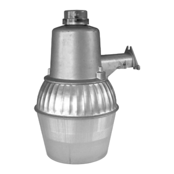
SKU Number: 356-7679
1 SOW HPS Yard Light
L1741PTDID
@
G.) 1 Lock Washer
H.) 1 Wire Compartment Cover
I.) Light Bulb
(f
J.) 3 Wire nuts
Advertisement
Table of Contents

Related Manuals for Patriot Lighting 356-7679


Summary of Contents for Patriot Lighting 356-7679
- Page 1 ·'Yatr1ot SKU Number: 356-7679 1 SOW HPS Yard Light L1741PTDID LIGHTING ® Questions, Problems, missing parts? Before returning to your retailer, call our customer service at 1-800-561-4321 Monday-Friday 8:00a.m. - 5:00p.m. CST PACKAGE CONTENTS HARDWARE CONTENTS Note: Hardware not shown to size �...
- Page 2 Photocell Photocell Wire Compartment Cover...
- Page 3 ASSEMBLY CONTINUED 3. Without the light in hand, start the two bottom lag screws (B) in the bottom two holes already drilled into the mounting surface. Tighten these two lag screws (B) with a wrench until there is slightly more space than the thickness of the cast mounting arm.
- Page 4 ASSEMBLY CONTINUED NOTE: Window or arrow on top of photocell should be pointed away from the mounting surface. Also, point North whenever possible. The receptacle/socket may be repositioned by loosening the screw in the center of the photocell receptacle/socket. Rotate to new position and retighten screw.
Need help?
Do you have a question about the 356-7679 and is the answer not in the manual?
Questions and answers