
Related Manuals for EWM UK 500


Summary of Contents for EWM UK 500
- Page 1 Operating instructions Air-cooling units for water-cooled welding torches UK 500 099-008026-EW501 Observe additional system documents! 9.9.2022...
- Page 2 +49 2680 181-0. A list of authorised sales partners can be found at www.ewm-group.com/en/specialist-dealers. Liability relating to the operation of this equipment is restricted solely to the function of the equipment. No other f orm of liability, regardless of type, shall be accepted.
-
Page 3: Table Of Contents
6.2.3 Annual test (inspection and testing during operation)........20 Disposing of equipment..................21 7 Rectifying faults ......................22 Checklist for rectifying faults ...................22 8 Technical data ......................23 UK 500 ........................23 9 Accessories.........................24 Welding torch cooling system..................24 9.1.1 Coolant - type blueCool ................24 9.1.2 Coolant - type KF..................24... -
Page 4: For Your Safety
For your safety Notes on using these operating instructions For your safety Notes on using these operating instructions DANGER Working or operating procedures which must be closely observed to prevent imminent serious and even fatal injuries. • Saf ety notes include the "DANGER" keyword in the heading with a general warning symbol. •... -
Page 5: Explanation Of Icons
For your safety Explanation of icons Explanation of icons Symbol Description Symbol Description Indicates technical aspects which the Activate and release / Tap / Tip user must observe. Switch off machine Release Switch on machine Press and hold Incorrect / Invalid Switch Correct / Valid Turn... -
Page 6: Safety Instructions
For your safety Saf ety instructions Safety instructions WARNING Risk of accidents due to non-compliance with the safety instructions! Non-compliance with the safety instructions can be fatal! • Caref ully read the safety instructions in this manual! • Observe the accident prevention regulations and any regional regulations! •... - Page 7 For your safety Saf ety instructions WARNING Risk of injury due to improper clothing! During arc welding, radiation, heat and voltage are sources of risk that cannot be avoided. The user has to be equipped with the complete personal protective equipment at all times.
- Page 8 For your safety Saf ety instructions CAUTION Smoke and gases! Smoke and gases can lead to breathing difficulties and poisoning. In addition, solvent vapour (chlorinated hydrocarbon) may be converted into poisonous phosgene due to the ultraviolet radiation of the arc! •...
-
Page 9: Transport And Installation
For your safety Transport and installation CAUTION Obligations of the operator! The respective national directives and laws must be complied with when operating the machine! • Implementation of national legislation relating to framework directive 89/391/EEC on the int- roduction of measures to encourage improvements in the safety and health of workers at work and associated individual guidelines. - Page 10 For your safety Transport and installation CAUTION Risk of accidents due to supply lines! During transport, attached supply lines (mains leads, control cables, etc.) can cause risks, e.g. by causing connected machines to tip over and injure persons! • Disconnect all supply lines before transport! Risk of tipping! There is a risk of the machine tipping over and injuring persons or being damaged itself during movement and set up.
-
Page 11: Intended Use
3.2.1 Warranty For more information refer to the "Warranty registration" brochure supplied and our information regarding warranty, maintenance and testing at www.ewm-group.com! 3.2.2 Declaration of Conformity This product corresponds in its design and construction to the EU directives listed in the decla- ration. -
Page 12: Machine Description - Quick Overview
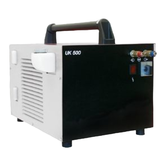
Machine description – quick overview Front view / rear view Machine description – quick overview Front view / rear view Figure 4-1 Item Symbol Description Carrying handle Coolant tank cap Upper filling level gauge Maximum coolant filling level Coolant tank > see 5.1.3 chapter Lower filling level gauge Minimum coolant filling level Cooling air inlet... - Page 13 Machine description – quick overview Front view / rear view Item Symbol Description Functional error signal light Lights up in case of pressure loss in the coolant circuit. Check coolant level and coolant circuit for leaks. Main Switch Switching the machine on or off. Quick connect coupling, blue Coolant supply to the welding torch Quick connect coupling, red...
-
Page 14: Design And Function
Design and function Transport and installation Design and function WARNING Risk of injury from electrical voltage! Contact with live parts, e.g. power connections, can be fatal! • Observe the safety information on the first pages of the operating instructions! • Commissioning must be carried out by persons who are specifically trained in handling power sources! •... -
Page 15: Welding Torch Cooling System
All inf ormation relates to the total hose package length of the complete welding system and presents exemplary configurations (of components of the EWM product portfolio with standard lengths). A straight kink-f ree installation is to be ensured, taking into account the max. delivery height. -
Page 16: Adding Coolant
Design and function Transport and installation 5.1.3.3 Adding coolant The unit is supplied ex works with a minimum level of coolant. Figure 5-1 Item Symbol Description Coolant tank cap Upper filling level gauge Maximum coolant filling level Coolant tank > see 5.1.3 chapter Lower filling level gauge Minimum coolant filling level •... -
Page 17: Mains Connection
Design and function Transport and installation 5.1.4 Mains connection DANGER Hazards caused by improper mains connection! An improper mains connection can cause injuries or damage property! • The connection (mains plug or cable), the repair or voltage adjustment of the device must be carried out by a qualified electrician in accordance with the respective local laws or nati- onal regulations! •... -
Page 18: Functional Characteristics
Design and function Functional characteristics Functional characteristics Overloading the coolant pump! The cooling unit must not be put into operation without a welding torch connected, as otherwise the coolant pump will be destroyed due to thermal overload (the coolant cannot circulate in the coolant circuit). -
Page 19: Maintenance, Care And Disposal
Maintenance, care and disposal General Maintenance, care and disposal General DANGER Risk of injury due to electrical voltage after switching off! Working on an open machine can lead to fatal injuries! Capacitors are loaded with electrical voltage during operation. Voltage remains present for up to four minutes after the mains plug is removed. -
Page 20: Maintenance Work, Intervals
A periodic test according to IEC 60974-4 "Periodic inspection and test" has to be carried out. In addition to the regulations on testing given here, the relevant local laws and regulations must also be observed. For more information refer to the "Warranty registration" brochure supplied and our information regarding warranty, maintenance and testing at www.ewm-group.com! 099-008026-EW501 9.9.2022... -
Page 21: Disposing Of Equipment
Inf ormation on returning used equipment or collections can be obtained from the respective municipal administration office. Devices can also be returned to EWM sales partners across Europe. Further inf ormation on the topic of the disposal of electrical and electronic equipment can be found on our website at: https://www.ewm-group.com/de/nachhaltigkeit.html. -
Page 22: Rectifying Faults
Rectifying faults Checklist for rectifying faults Rectifying faults All products are subject to rigorous production checks and final checks. If , despite this, something fails to work at any time, please check the product using the following flowchart. If none of the fault rectification procedures described leads to the correct functioning of the product, please inform your authorised dea- ler. -
Page 23: Technical Data
Technical data UK 500 Technical data The limit value determination of technical data results from considering the combined overall system (cooling unit and welding machine). UK 500 Supply voltage (from the welding machine) 230 V Frequency 50/60 Hz Cooling capacity at 1 l/min (+25°C/77°F) 1200 W max. -
Page 24: Accessories
Accessories Welding torch cooling system Accessories Welding torch cooling system Type Designation Item no. UKV4SET 4M Hose connection set 092-000587-00000 HOSE BRIDGE UNI Tube bridge 092-007843-00000 9.1.1 Coolant - type blueCool Type Designation Item no. blueCool -10 5 l Coolant up to -10 °C (14 °F), 5 l 094-024141-00005 blueCool -10 25 l Coolant up to -10 °C (14 °F), 25 l... -
Page 25: Appendix
Appendix Searching for a dealer Appendix 10.1 Searching for a dealer Sales & service partners www.ewm-group.com/en/specialist-dealers "More than 400 EWM sales partners worldwide" 099-008026-EW501 9.9.2022...
Need help?
Do you have a question about the UK 500 and is the answer not in the manual?
Questions and answers