
Related Manuals for EWM Taurus 355 Synergic S HP MM TKM


Summary of Contents for EWM Taurus 355 Synergic S HP MM TKM
- Page 1 Operating instructions Welding machine Taurus 355 Synergic S HP MM TKM 099-005407-EW501 Observe additional system documents! 8.2.2022...
- Page 2 +49 2680 181-0. A list of authorised sales partners can be found at www.ewm-group.com/en/specialist-dealers. Liability relating to the operation of this equipment is restricted solely to the function of the equipment. No other form of liability, regardless of type, shall be accepted.
-
Page 3: Table Of Contents
Contents Notes on using these operating instructions Contents 1 Contents ............................3 2 For your safety ..........................7 Notes on using these operating instructions ................7 Explanation of icons ....................... 8 Safety instructions ........................9 Transport and installation ....................12 3 Intended use .......................... - Page 4 Contents Notes on using these operating instructions 5.3.6.3 Burn-back ....................42 5.3.7 Welding power (operating point) ................43 5.3.7.1 Operating point setting via welding current, material thickness or wire feed speed ..................... 43 5.3.7.2 Arc length ....................43 5.3.7.3 Accessory components for operating point setting ....... 43 5.3.8 forceArc .........................
- Page 5 Contents Notes on using these operating instructions 5.11.3.3 Display mode for Up/Down welding torch with one-digit 7-segment display (P3) ................... 79 5.11.3.4 Program limit (P4) ................. 79 5.11.3.5 Special cycle in the operating modes special latched and non-latched (P5)......................79 5.11.3.6 Correction operation, threshold value setting (P7) .......
- Page 6 Contents Notes on using these operating instructions Computer communication ....................101 Networking / Xnet ....................... 102 10 Replaceable parts ........................103 10.1 Wire feed rollers ......................... 103 10.1.1 Wire feed rollers for steel wire ................103 10.1.2 Wire feed rollers for aluminium wire ..............103 10.1.3 Wire feed rollers for cored wire ................
-
Page 7: For Your Safety
For your safety Notes on using these operating instructions For your safety Notes on using these operating instructions DANGER Working or operating procedures which must be closely observed to prevent imminent serious and even fatal injuries. • Safety notes include the "DANGER" keyword in the heading with a general warning symbol. •... -
Page 8: Explanation Of Icons
For your safety Explanation of icons Explanation of icons Symbol Description Symbol Description Indicates technical aspects which the u- Activate and release / Tap / Tip ser must observe. Switch off machine Release Switch on machine Press and hold Switch Incorrect / Invalid Turn Correct / Valid... -
Page 9: Safety Instructions
For your safety Safety instructions Safety instructions WARNING Risk of accidents due to non-compliance with the safety instructions! Non-compliance with the safety instructions can be fatal! • Carefully read the safety instructions in this manual! • Observe the accident prevention regulations and any regional regulations! •... - Page 10 For your safety Safety instructions WARNING Risk of injury due to improper clothing! During arc welding, radiation, heat and voltage are sources of risk that cannot be avoided. The user has to be equipped with the complete personal protective equipment at all times.
- Page 11 For your safety Safety instructions CAUTION Smoke and gases! Smoke and gases can lead to breathing difficulties and poisoning. In addition, solvent vapour (chlorinated hydrocarbon) may be converted into poisonous phosgene due to the ultraviolet radiation of the arc! • Ensure that there is sufficient fresh air! •...
-
Page 12: Transport And Installation
For your safety Transport and installation CAUTION Obligations of the operator! The respective national directives and laws must be complied with when operating the machine! • Implementation of national legislation relating to framework directive 89/391/EEC on the int- roduction of measures to encourage improvements in the safety and health of workers at work and associated individual guidelines. - Page 13 For your safety Transport and installation CAUTION Risk of accidents due to supply lines! During transport, attached supply lines (mains leads, control cables, etc.) can cause risks, e.g. by causing connected machines to tip over and injure persons! • Disconnect all supply lines before transport! Risk of tipping! There is a risk of the machine tipping over and injuring persons or being damaged itself during movement and set up.
-
Page 14: Intended Use
3.3.1 Warranty For more information refer to the "Warranty registration" brochure supplied and our information regarding warranty, maintenance and testing at www.ewm-group.com! 3.3.2 Declaration of Conformity This product corresponds in its design and construction to the EU directives listed in the decla- ration. -
Page 15: Service Documents (Spare Parts And Circuit Diagrams)
Intended use Documents which also apply 3.3.4 Service documents (spare parts and circuit diagrams) WARNING Do not carry out any unauthorised repairs or modifications! To avoid injury and equipment damage, the unit must only be repaired or modified by specialist, skilled persons! The warranty becomes null and void in the event of unauthorised interference. -
Page 16: Machine Description - Quick Overview
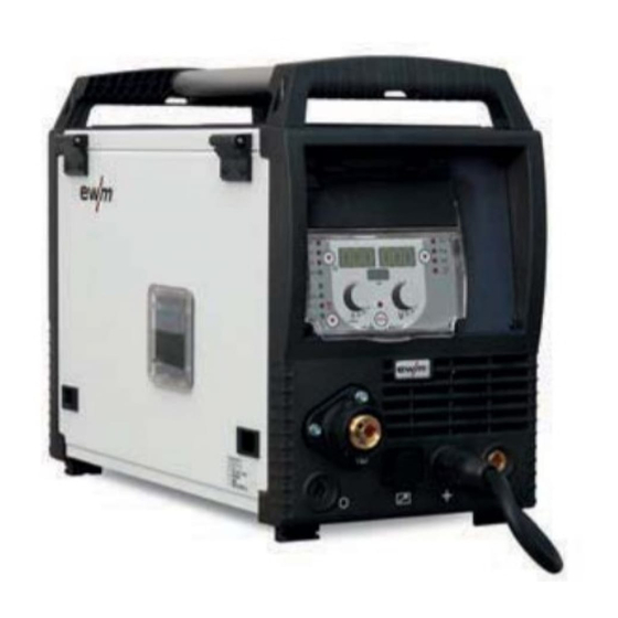
Machine description – quick overview Front view / rear view Machine description – quick overview Front view / rear view The device configuration shown may differ in case of an additional ex works options or retrofitting options > see 9 chapter. Figure 4-1 099-005407-EW501 8.2.2022... - Page 17 Machine description – quick overview Front view / rear view Item Symbol Description Carrying handle Machine control > see 4.3 chapter 19-pole connection socket (analogue) For connecting analogue accessory components (remote control, welding torch control lead, etc.) Welding torch connection (Euro or Dinse torch connector) Welding current, shielding gas and torch trigger integrated Park socket, polarity selection plug Retainer for the polarity selection plug in MMA mode or for transport.
-
Page 18: Inside View
Machine description – quick overview Inside view Inside view Figure 4-2 Item Symbol Description Protective cap Cover for the wire feed mechanism and other operating elements. Depending on the machine series, there are added information stickers on the inside of the flap for the operation and maintenance of the machine. -
Page 19: Operating Elements In The Machine
Machine description – quick overview Inside view 4.2.1 Operating elements in the machine Figure 4-3 Item Symbol Description Key button, automatic cutout Wire feed motor supply voltage fuse press to reset a triggered fuse Welding torch function changeover switch (special welding torch required) ---- Changing over programs or JOBs ---- Infinite adjustment of welding performance. -
Page 20: Machine Control - Operating Elements
Machine description – quick overview Machine control – Operating elements Machine control – Operating elements Figure 4-4 Item Symbol Description Functional sequence > see 4.3.1 chapter Push-button, welding task selection (JOB) Select the welding task using the welding task list (JOB-LIST) (not applicable for Phoe- nix Expert). - Page 21 Machine description – quick overview Machine control – Operating elements Item Symbol Description Operating modes push-button (functional sequences) > see 5.3.10 chapter --------- Non-latched ------- Latched --------- Signal light turns green: Special non-latched ---- Signal light turns red: MIG spots --------- Special latched Push-button, throttling effect (arc dynamics) ----- Arc is harder and more narrow...
-
Page 22: Function Sequence
Machine description – quick overview Machine control – Operating elements 4.3.1 Function sequence Figure 4-5 Item Symbol Description Select welding parameters button This button is used to select the welding parameters depending on the welding process and operating mode used. Signal light, gas pre-flow time Setting range 0.0 s to 20.0 s Signal light, start program (P... -
Page 23: Welding Data Display
Machine description – quick overview Machine control – Operating elements 4.3.2 Welding data display To the left and right of the control displays are the "Parameter selection" buttons ( ). They are used to select welding parameters to be displayed. Each press of the button advances the display to the next parameter (LEDs next to the button indicate the selection). -
Page 24: Design And Function
Design and function General Design and function General WARNING Risk of injury from electrical voltage! Contact with live parts, e.g. power connections, can be fatal! • Observe the safety information on the first pages of the operating instructions! • Commissioning must be carried out by persons who are specifically trained in handling power sources! •... -
Page 25: Transport And Installation
Design and function Transport and installation Transport and installation WARNING Risk of accident due to improper transport of machines that must not be lifted! Do not lift or suspend the machine! The machine can drop and cause injuries! The handles, straps or brackets are suitable for transport by hand only! •... -
Page 26: Notes On The Installation Of Welding Current Leads
Design and function Transport and installation 5.2.4 Notes on the installation of welding current leads • Incorrectly installed welding current leads can cause faults in the arc (flickering). • Lay the workpiece lead and hose package of power sources without HF igniter (MIG/MAG) for as long and as close as possible in parallel. -
Page 27: Stray Welding Currents
Design and function Transport and installation 5.2.5 Stray welding currents WARNING Risk of injury due to stray welding currents! Stray welding currents can destroy protective earth conductors, damage machines and electronic devices and cause overheating of components, leading to fire. •... -
Page 28: Mains Connection
Design and function Transport and installation 5.2.6 Mains connection DANGER Hazards caused by improper mains connection! An improper mains connection can cause injuries or damage property! • The connection (mains plug or cable), the repair or voltage adjustment of the device must be carried out by a qualified electrician in accordance with the respective local laws or nati- onal regulations! •... -
Page 29: Shielding Gas Supply (Shielding Gas Cylinder For Welding Machine)
Design and function Transport and installation 5.2.7 Shielding gas supply (shielding gas cylinder for welding machine) WARNING Risk of injury due to improper handling of shielding gas cylinders! Improper handling and insufficient securing of shielding gas cylinders can cause serious injuries! •... -
Page 30: Shielding Gas Hose Connection
Design and function Transport and installation 5.2.7.2 Shielding gas hose connection Figure 5-7 Item Symbol Description Connection thread - G¼" Shielding gas connection (inlet) • Screw the gas hose connection to the shielding gas connection (inlet) on the machine gas-tight. 5.2.7.3 Shielding gas volume settings If the shielding gas setting is too low or too high, this can introduce air to the weld pool and may cause... -
Page 31: Gas Test
Design and function Transport and installation 5.2.7.4 Gas test Figure 5-8 5.2.7.5 Purge hose package 300s Figure 5-9 5.2.8 Welding torch cooling system 5.2.8.1 Cooling unit connection Figure 5-10 Item Symbol Description Cooling module 4-pole connection socket Cooling unit voltage supply 8-pole connection socket Cooling unit control lead 099-005407-EW501... -
Page 32: Welding Torch Holder
Design and function Transport and installation • Insert and lock the 4-pole supply plug on the cooling unit into the 4-pole connection socket on the welding machine. • Insert and lock the 8-pole control lead plug on the cooling unit into the 8-pole connection socket on the welding machine. -
Page 33: Protective Flap, Welding Machine Control
Design and function Transport and installation 5.2.10 Protective flap, welding machine control Figure 5-12 Item Symbol Description Protective cap Bracket, protective cap • Push the right-hand bracket of the protective cap to the right and remove the protective cap. 5.2.11 Dirt filter These accessory components can be retrofitted as an option >... -
Page 34: Mig/Mag Welding
Design and function MIG/MAG welding MIG/MAG welding 5.3.1 Assemble the wire guide The Euro torch connector is factory-fitted with a guide tube for welding torches with steel liner. Conver- sion is necessary if a welding torch with a steel liner is used! •... -
Page 35: Welding Torch And Workpiece Line Connection
Design and function MIG/MAG welding 5.3.2 Welding torch and workpiece line connection Figure 5-15 Item Symbol Description Welding torch Polarity selector plug, welding current cable Internal welding current cable for central connection/welding torch. • ----------- Connection socket for “+” welding current Workpiece •... -
Page 36: Inserting The Wire Spool
Design and function MIG/MAG welding 5.3.3.1 Inserting the wire spool CAUTION Risk of injury due to incorrectly secured wire spool. If the wire spool is not secured properly, it may come loose from the wire spool support and fall to the ground, causing damage to the machine and injuries. •... -
Page 37: Changing The Wire Feed Rollers
Design and function MIG/MAG welding 5.3.3.2 Changing the wire feed rollers Figure 5-18 Item Symbol Description Tommy The tommy is used to secure the closure brackets of the wire feed rollers. Closure bracket The closure brackets are used to secure the wire feed rollers. Feed roll tensioner Fixing the clamping unit and setting the pressure. - Page 38 Design and function MIG/MAG welding Unsatisfactory welding results due to faulty wire feeding! The wire feed rolls must be suitable for the diameter of the wire and the material. The wire feed rolls are colour-coded to facilitate distinction (see the Wire feed roll overview table). When working with a wire diameter of >...
-
Page 39: Inching The Wire Electrode
Design and function MIG/MAG welding 5.3.3.3 Inching the wire electrode CAUTION Risk of injury due to welding wire escaping from the welding torch! The welding wire can escape from the welding torch at high speed and cause bodily in- jury including injuries to the face and eyes! •... -
Page 40: Spool Brake Setting
Design and function MIG/MAG welding • The contact pressure has to be adjusted separately for each side (wire inlet/outlet) at the feed roll ten- sioner setting nuts depending on the welding consumable used. A table with the setting values can be found on a sticker near the wire drive. -
Page 41: Definition Of Mig/Mag Welding Tasks
Design and function MIG/MAG welding 5.3.4 Definition of MIG/MAG welding tasks This machine series offers user-friendly operation and a multitude of features. • Various welding tasks (JOBs) consisting of welding procedure, material type, wire diameter and shiel- ding gas type have been predefined > see 11.1 chapter. •... -
Page 42: Superpuls
(PB). This function is e.g. used for thin sheet welding to reduce the heat input in a controlled manner or for positional welding without the need for weaving. The combination of superPuls and other EWM welding processes offers a multitude of possibilities. For example, to enable the welding of vertical-up welds without the "Christmas tree" technique, when selec- ting program 1 >... -
Page 43: Welding Power (Operating Point)
Design and function MIG/MAG welding 5.3.7 Welding power (operating point) The welding power is adjusted according to the principle of one-knob operation. The user can set their operating point optionally as wire feed speed, welding current or material thickness. The optimum welding voltage for the operating point is calculated and set by the welding machine. -
Page 44: Forcearc
Design and function MIG/MAG welding 5.3.8 forceArc Heat-reduced, directionally-stable and powerful arc with deep fusion penetration for the upper power range. Figure 5-28 • Smaller included angle due to deep penetration and directionally stable arc • Excellent root and sidewall fusion •... -
Page 45: Rootarc
Design and function MIG/MAG welding 5.3.9 rootArc Short arc with perfect weld modelling capabilities for effortless gap bridging, especially for root welding Figure 5-29 • Reduced spatter compared to standard short arc • Good root formation and secure sidewall fusion •... - Page 46 Design and function MIG/MAG welding Non-latched mode Figure 5-30 Step 1 • Press and hold torch trigger. • Shielding gas is expelled (gas pre-flows). • Wire feed motor runs at “creep speed”. • Arc ignites after the wire electrode makes contact with the workpiece; welding current flows. •...
- Page 47 Design and function MIG/MAG welding Non-latched operation with superpulse Figure 5-31 Step 1 • Press and hold torch trigger. • Shielding gas is expelled (gas pre-flows). • Wire feed motor runs at “creep speed”. • Arc ignites after the wire electrode makes contact with the workpiece; welding current flows. •...
- Page 48 Design and function MIG/MAG welding Special, non-latched Figure 5-32 Step 1 • Press and hold torch trigger • Shielding gas is expelled (gas pre-flows) • Wire feed motor runs at “creep speed”. • Arc ignites after the wire electrode makes contact with the workpiece, welding current is flowing (start program P for the time t START...
- Page 49 Design and function MIG/MAG welding Spot welding Figure 5-33 The ignition time t must be added to the spot time t start 1st cycle • Press and hold torch trigger • Shielding gas is expelled (gas pre-flows) • Wire feed motor runs at "creep speed" •...
- Page 50 Design and function MIG/MAG welding Special, non-latched with superpulse Figure 5-34 Step 1 • Press and hold torch trigger • Shielding gas is expelled (gas pre-flows) • Wire feed motor runs at “creep speed”. • Arc ignites after the wire electrode makes contact with the workpiece, welding current is flowing (start program P for the time t START...
- Page 51 Design and function MIG/MAG welding Latched mode Figure 5-35 Step 1 • Press and hold torch trigger • Shielding gas is expelled (gas pre-flows) • Wire feed motor runs at “creep speed”. • Arc ignites after the wire electrode makes contact with the workpiece; welding current flows. •...
- Page 52 Design and function MIG/MAG welding Latched mode with superpulse Figure 5-36 Step 1: • Press and hold torch trigger • Shielding gas is expelled (gas pre-flows) • Wire feed motor runs at “creep speed”. • Arc ignites after the wire electrode makes contact with the workpiece; welding current flows. •...
- Page 53 Design and function MIG/MAG welding Latched special Figure 5-37 Step 1 • Press and hold torch trigger • Shielding gas is expelled (gas pre-flows) • Wire feed motor runs at “creep speed”. • Arc ignites after the wire electrode makes contact with the workpiece, welding current is flowing (start program P START Step 2...
- Page 54 Design and function MIG/MAG welding Special, latched with superpulse Figure 5-38 Step 1 • Press and hold torch trigger • Shielding gas is expelled (gas pre-flows) • Wire feed motor runs at “creep speed”. • Arc ignites after the wire electrode makes contact with the workpiece, welding current is flowing (start program P for the time t START...
-
Page 55: Mig/Mag Program Sequence ("Program Steps" Mode)
Design and function MIG/MAG welding 5.3.11 MIG/MAG program sequence ("Program steps" mode) Certain materials, aluminium for example, require special functions for reliable and high-quality welding. In this case, the special latched mode is used with the following programs: • Start program P (avoidance of cold welds at start of seam) START •... -
Page 56: Mig/Mag Overview Of Parameters
Design and function MIG/MAG welding 5.3.11.2 MIG/MAG overview of parameters Figure 5-41 Basic Parameters Item Meaning / Explanation Setting Range Gas pre-flow time 0.0s to 20.0s : Wire speed, relative 1% to 200% START Arc length correction -9.9V to +9.9V Duration 0.0s to 20.0s Slope duration from P... -
Page 57: Example, Tack Welding (Non-Latched)
Design and function MIG/MAG welding 5.3.11.3 Example, tack welding (non-latched) Figure 5-42 Basic parameters Parameter Meaning / explanation Setting range GASstr Gas pre-flow time 0.0s to 20.0s GASend: Gas post-flow time 0.0s to 20s RUECK Wire burn-back length 2 to 500 "P "... -
Page 58: Example, Aluminium Welding (Latched Special)
Design and function MIG/MAG welding 5.3.11.5 Example, aluminium welding (latched special) Figure 5-44 Basic parameters Welding parameter Meaning / explanation Setting range GASstr Gas pre-flow time 0.0s to 20.0s GASend: Gas post-flow time 0.0s to 20.0s RUECK Wire burn-back length 2 to 500 "P "... -
Page 59: Example, Visible Seams (Latched Super Pulse)
Design and function MIG/MAG welding 5.3.11.6 Example, visible seams (latched super pulse) Figure 5-45 Basic parameters Welding parameter Meaning / explanation Setting range GASstr Gas pre-flow time 0.0s to 20.0s GASend: Gas post-flow time 0.0s to 20.0s RUECK Wire burn-back length 2 to 500 "P "... -
Page 60: Main Program A Mode
Design and function MIG/MAG welding 5.3.12 Main program A mode Different welding tasks or positions on a workpiece demand various welding performances (operating points) or welding programs. The following parameters are stored in each of the up to 16 programs: •... -
Page 61: Selecting Parameters (Program A)
Design and function MIG/MAG welding Figure 5-47 Example 3: Aluminium welding of different sheet metal thicknesses (non-latched or latched special) Figure 5-48 Up to 16 programs (P to P ) can be defined. An operating point (wire speed, arc length correction, dynamics/choke effect) can be defined permanently in each program. -
Page 62: Standard Mig/Mag Torch
Design and function MIG/MAG welding 5.3.13 Standard MIG/MAG torch The MIG welding torch trigger is essentially used to start and stop the welding process. Operating elements Functions Torch trigger • Start/stop welding Additional functions such as program switching (before or after welding) are possible by tapping the torch trigger (depending on machine type and control configuration). -
Page 63: Expert Menu (Mig/Mag)
Design and function MIG/MAG welding 5.3.15 Expert menu (MIG/MAG) The Expert menu has adjustable parameters stored that don’t require regular setting. The number of pa- rameters shown may be limited, e.g. if a function is deactivated. 5.3.15.1 Selection Figure 5-51 Display Setting/selection Burn-back time >... -
Page 64: Programme Limit
Design and function MMA welding Display Setting/selection Pulse arc welding process (program P The pulse arc welding process can be activated in the end program (P ) with the spe- cial non-latched and special latched operating modes. ------- Function activated. ------- Function deactivated. -
Page 65: Welding Task Selection
Design and function MMA welding • Insert the polarity selection plug in the park socket and lock in place by turning to the right. • Insert the electrode holder plug and workpiece lead into the welding current socket depending on ap- plication and lock in place by turning to the right. -
Page 66: Hotstart
Design and function MMA welding 5.4.5 Hotstart The function hot start ensures a secure igniting of the arc and a sufficient heating to the still cold parent metal at the beginning of the welding process. The ignition takes place here with increased current (hot start current) over a certain time (hot start time). -
Page 67: Tig Welding
Design and function TIG welding TIG welding 5.5.1 Preparing the TIG welding torch The TIG welding torch is to be equipped to suit the relevant welding task! • Fit suitable tungsten electrodes and • an appropriate shielding gas nozzle. • Observe the operating instructions for the TIG welding torch! 5.5.2 Welding torch and workpiece line connection... -
Page 68: Welding Current Setting
Design and function TIG welding 5.5.4 Welding current setting Figure 5-61 5.5.5 Arc ignition 5.5.5.1 Liftarc Figure 5-62 The arc ignites through contact with the workpiece: a) Carefully place the torch gas nozzle and tungsten electrode tip against the workpiece (lift arc current flows independent of the set main current) b) Angle the torch above the torch gas nozzle until the distance between electrode tip and workpiece is approx. -
Page 69: Operating Modes (Functional Sequences)
Design and function TIG welding 5.5.6 Operating modes (functional sequences) 5.5.6.1 Explanation of signs and functions Symbol Meaning Press torch trigger Release torch trigger Tap torch trigger (press briefly and release) Shielding gas flowing Welding output Gas pre-flows Gas post-flows Non-latched Special, non-latched Latched... - Page 70 Design and function TIG welding Non-latched mode Figure 5-63 Selection • Select non-latched operating mode Step 1 • Press and hold torch trigger. • Shielding gas is expelled (gas pre-flows). The arc is ignited using liftarc. • Welding current flows with pre-selected setting. Step 2 •...
- Page 71 Design and function TIG welding Latched mode Figure 5-65 Selection • Select latched operating mode Step 1 • Press and hold torch trigger • Shielding gas is expelled (gas pre-flows) The arc is ignited using liftarc. • Welding current flows with pre-selected setting. Step 2 •...
- Page 72 Design and function TIG welding Latched special Figure 5-66 Selection • Select latched special mode Step 1 • Press and hold torch trigger. • Shielding gas is expelled (gas pre-flows). The arc is ignited using liftarc. • Welding gas flows at pre-selected setting in start program "P ".
-
Page 73: Tig Program Sequence ("Program Steps" Mode)
Design and function Access control 5.5.7 TIG program sequence ("Program steps" mode) Figure 5-67 Basic parameters Item Meaning/explanation Setting range Gas pre-flow time 0 s to 0.9 s START 0% to 200% Start current Duration (start program) 0 s to 20 s Slope duration from P to P 0 s to 20 s... -
Page 74: Power-Saving Mode (Standby)
Design and function Power-saving mode (Standby) Power-saving mode (Standby) You can activate the power-saving mode by either pressing the push-button > see 4.3 chapter for a pro- longed time or by setting a parameter in the machine configuration menu (time-controlled power-saving mode ) >... -
Page 75: Rint X12 Robot Interface
Design and function PC interface 5.9.2 RINT X12 robot interface The standard digital interface for mechanised applications Functions and signals: • Digital inputs: start/stop, operating modes, JOB and program selection, inching, gas test • Analogue inputs: control voltages, e.g. for welding performance, welding current, etc. •... -
Page 76: Special Parameters (Advanced Settings)
Design and function Special parameters (advanced settings) 5.11 Special parameters (advanced settings) Special parameters (P1 to Pn) are applied for customer-specific configuration of machine functions. This allows the user maximum flexibility in optimising their requirements. These settings are not configured directly on the machine control since a regular setting of the parame- ters is generally not required. - Page 77 Design and function Special parameters (advanced settings) Display Setting/selection Correction operation, threshold value setting 0 = --------correction operation switched off (Ex works) 1 = --------correction operation on "Main program (PA)" flashing Program switching with standard welding torch No program switching (factory setting) 1 = --------Special latched 2 = --------Special latched (n-cycle active) 3 = --------Special latched (n-cycle sequence from any program)
-
Page 78: Reset To Factory Settings
Design and function Special parameters (advanced settings) Display Setting/selection Predefined absolute value for relative programs Start program (P ), down-slope program (P ) and end program (P ) can be set re- START lative to the main program (P ) or in an absolute manner, as desired. 0 = ------- Relative parameter setting (ex factory) 1 = ------- Absolute parameter setting Electronic gas flow control, type... -
Page 79: Special Parameters In Detail
Design and function Special parameters (advanced settings) 5.11.3 Special parameters in detail 5.11.3.1 Ramp time for wire inching (P1) The wire inching starts with a speed 1.0 m/min for 2 secs. It is subsequently increased to a ramp function to 6.0 m/min. The ramp time can be set between two ranges. During wire inching, the speed can be changed by means of the welding power rotary knob. -
Page 80: Correction Operation, Threshold Value Setting (P7)
Design and function Special parameters (advanced settings) 5.11.3.6 Correction operation, threshold value setting (P7) The correction operation is switched on and off for all JOBs and their programs at the same time. A cor- rection operation is specified for wire speed (DV) and welding voltage correction (Ukorr) for each JOB. The correction value is saved separately for each program. -
Page 81: Switching Programs With The Standard Torch Trigger (P8)
Design and function Special parameters (advanced settings) 5.11.3.7 Switching programs with the standard torch trigger (P8) Special latched (latched absolute program sequence) • Cycle 1: absolute program 1 is run • Cycle 2: absolute program 2 is run after completion of "tstart". •... -
Page 82: Latched/Special-Latched Tap Start (P9)
Design and function Special parameters (advanced settings) The number of programs (P ) corresponds to the cycle number specified under N cycle. 1st cycle • Press and hold torch trigger. • Shielding gas is expelled (gas pre-flows). • Wire feed motor runs at "creep speed". •... -
Page 83: Job List Switching (P12)
Design and function Special parameters (advanced settings) 5.11.3.11 JOB list switching (P12) Name Explanation Task-based JOB numbers are sorted by welding wires and shielding gases. When JOB list selecting, the JOB numbers may be skipped. JOB numbers correspond to the actual memory cells. Every job can Real JOB list be selected, there will be no memory cells if the selection will be skip- ped. -
Page 84: Lower And Upper Limits Of The Remote Job Changeover Process (P13, P14)
Design and function Special parameters (advanced settings) By repeating the last two steps, the same source JOB can be copied to multiple target JOBs. If the control does not register any user activity for longer than 5 seconds, the parameter display is shown once more and the copy process is complete. -
Page 85: Selecting Programs With The Standard Torch Trigger (P17)
Design and function Special parameters (advanced settings) 5.11.3.15 Selecting programs with the standard torch trigger (P17) Allows you to select a program or switch a program before starting welding. You switch to the next program by tapping the torch trigger. Once the last enabled program is reached, you start again at the beginning. -
Page 86: Correction Or Nominal Voltage Display (P24)
Design and function Special parameters (advanced settings) 5.11.3.22 Correction or nominal voltage display (P24) When setting the arc correction using the right-hand rotary knob the display will either show the correction voltage +- 9.9 V (ex works) or the absolute nominal voltage. 5.11.3.23 JOB selection in Expert mode (P25) The special parameter P25 can be used to specify whether the special JOBs SP1/2/3 or the welding job selection according to the JOB list can be selected on the wire feeder. -
Page 87: Machine Configuration Menu
Design and function Machine configuration menu 5.12 Machine configuration menu Figure 5-77 Display Setting/selection Lead resistance 1 Lead resistance for the first welding circuit 0 mΩ–60 mΩ (8 mΩ ex works). Lead resistance 2 Lead resistance for the second welding circuit 0 mΩ–60 mΩ (8 mΩ ex works). Only qualified service personnel may change the parameters! Only qualified service personnel may change the parameters! Time-based power-saving mode >... -
Page 88: Aligning The Cable Resistance
Design and function Machine configuration menu 5.12.1 Aligning the cable resistance The resistance value of cables can either be set directly or it can be aligned using the power source. The factory setting of the power sources is 8 mΩ. This value correponds to a 5 m earth cable, a 1.5 m inter- mediate hose package and a 3 m water-cooled welding torch. -
Page 89: Power-Saving Mode (Standby)
Design and function Power-saving mode (Standby) 1 Preparation • Switch off the welding machine. • Unscrew the gas nozzle from the welding torch. • Trim the welding wire, so that it is flush with the contact tip. • Retract the welding wire a little (approx. 50 mm) on the wire feeder. There should now be no more welding wire in the contact tip. -
Page 90: Maintenance, Care And Disposal
Maintenance, care and disposal General Maintenance, care and disposal General DANGER Risk of injury due to electrical voltage after switching off! Working on an open machine can lead to fatal injuries! Capacitors are loaded with electrical voltage during operation. Voltage remains present for up to four minutes after the mains plug is removed. -
Page 91: Explanation Of Icons
Maintenance, care and disposal Explanation of icons Explanation of icons Person Welder / operator Service staff / expert, qualified person Test Visual inspection Functional check Period, interval One-shift operation Multi-shift operation every 8 hours Daily Weekly Monthly Every 6 months Annually 099-005407-EW501 8.2.2022... -
Page 92: Maintenance Schedule
Maintenance, care and disposal Maintenance schedule Maintenance schedule Maintenance step Only personnel designated as inspectors or repairers due to their trai- ning are allowed to carry out the relevant work step! Non-applicable in- spection points are omitted. • Check and clean the welding torch. Deposits in the welding torch may cause short circuits, impair the welding result and lead to welding torch damage! •... -
Page 93: Disposing Of Equipment
Information on returning used equipment or collections can be obtained from the respective municipal administration office. Devices can also be returned to EWM sales partners across Europe. Further information on the topic of the disposal of electrical and electronic equipment can be found on our website at: https://www.ewm-group.com/de/nachhaltigkeit.html. -
Page 94: Rectifying Faults
Rectifying faults Error messages (power source) Rectifying faults All products are subject to rigorous production checks and final checks. If, despite this, something fails to work at any time, please check the product using the following flowchart. If none of the fault rectification procedures described leads to the correct functioning of the product, please inform your authorised dea- ler. - Page 95 Rectifying faults Error messages (power source) Category Possible cause Remedy ID number allocation error Correct ID numbers (2DV) Detection of wire feeder 2 Check cable connections Error in open circuit voltage Inform Service. reduction (VRD) Overcurrent detection on wire Check ease of wire feeding feeder Error in tachometer generator Check the connection and particularly the ta-...
-
Page 96: Checklist For Rectifying Faults
Rectifying faults Checklist for rectifying faults Checklist for rectifying faults The correct machine equipment for the material and process gas in use is a fundamental requirement for perfect operation! Legend Symbol Description Fault/Cause Remedy Functional errors Mains fuse triggers - unsuitable mains fuse Set up recommended mains fuse >... -
Page 97: Vent Coolant Circuit
Rectifying faults Vent coolant circuit Vent coolant circuit Figure 7-1 • Switch off the machine and fill the coolant tank to the maximum level. • Unlock the quick-connect coupling with a suitable tool (connection open). To vent the cooling system always use the blue coolant connection, which is located as deep as possible inside the system (close to the coolant tank)! Figure 7-2 •... -
Page 98: Resetting Jobs (Welding Tasks) To The Factory Settings
Rectifying faults Resetting JOBs (welding tasks) to the factory settings Resetting JOBs (welding tasks) to the factory settings All customised welding parameters that are stored will be replaced by the factory settings. 7.4.1 Resetting a single JOB ENTER RESET EXIT Figure 7-3 7.4.2 Resetting all JOBs... -
Page 99: Technical Data
Technical data Taurus 355 Synergic S Technical data Taurus 355 Synergic S Performance specifications and guarantee only in connection with original spare and replacement parts! MIG/MAG Welding current (I 5 A to 350 A Welding voltage according to stan- 14,3 V to 31,5 V 10,2 V to 24,0 V 20,2 V to 34,0 V dard (U... -
Page 100: Accessories
Accessories Welding torch cooling system Accessories Performance-dependent accessories like torches, workpiece leads, electrode holders or intermediate hose packages are available from your authorised dealer. Welding torch cooling system Type Designation Item no. cool50 U40 Cooling module 090-008598-00502 cool50-2 U42 Cooling unit with reinforced pump 090-008797-00502 HOSE BRIDGE UNI Tube bridge... -
Page 101: General Accessories
Accessories General accessories General accessories Type Designation Item no. AK300 Wire spool adapter K300 094-001803-00001 CA D200 Centering adapter for 5-kg spools 094-011803-00000 16A 5POLE/CEE Mains plug 094-000712-00000 DM 842 Ar/CO2 230bar 30l D Pressure regulator with manometer 394-002910-00030 G1 G1/4 R 3M Gas hose 094-000010-00003 Sharpener for liner... -
Page 102: Networking / Xnet
Accessories Networking / Xnet Networking / Xnet Type Designation Item no. Xnet LAN Gateway LAN gateway in external casing 090-008833-00502 Xnet WiFi Gateway WiFi gateway in external casing 090-008834-00502 Xnet Extended-Set LAN Xnet retrofit set LAN: One machine licence, a LAN 091-008833-00001 gateway and a network cable (10 m) Xnet retrofit set WiFi: One machine licence, one... -
Page 103: Replaceable Parts
Replaceable parts Wire feed rollers Replaceable parts Performance specifications and guarantee only in connection with original spare and replacement parts! 10.1 Wire feed rollers 10.1.1 Wire feed rollers for steel wire Type Designation Item no. FE 4R 0.6 MM/0.023 INCH Drive roll set, 37 mm, 4 rolls, V-groove for steel, 092-002770-00006 LIGHT PINK... -
Page 104: Wire Feed Rollers For Cored Wire
Replaceable parts Wire feed rollers 10.1.3 Wire feed rollers for cored wire Type Designation Item no. FUEL 4R 0.8 MM/0.03 INCH Drive roll set, 37 mm, 4 rolls, V-groove/knurled for 092-002848-00008 WHITE/ORANGE flux cored wire FUEL 4R 1.0 MM/0.04 INCH Drive roll set, 37 mm, 4 rolls, V-groove/knurled for 092-002848-00010 BLUE/ORANGE... -
Page 105: Appendix
Appendix JOB-List Appendix 11.1 JOB-List Figure 11-1 099-005407-EW501 8.2.2022... -
Page 106: Parameter Overview - Setting Ranges
Appendix Parameter overview – setting ranges 11.2 Parameter overview – setting ranges 11.2.1 MIG/MAG welding Name Display Setting range Start current Correction of arc length in start program P -9,9 START Slope time of start program P to main program P START Slope time of main program P to end program P... -
Page 107: Searching For A Dealer
Appendix Searching for a dealer 11.3 Searching for a dealer Sales & service partners www.ewm-group.com/en/specialist-dealers "More than 400 EWM sales partners worldwide" 099-005407-EW501 8.2.2022...
Need help?
Do you have a question about the Taurus 355 Synergic S HP MM TKM and is the answer not in the manual?
Questions and answers