Advertisement
Quick Links
Advertisement

Subscribe to Our Youtube Channel
Related Manuals for RTS RMS300


Summary of Contents for RTS RMS300
- Page 1 PACKAGE I OIN TDP3504 9300-3504-00 I September Third Edition 1989 Rack Mount Speaker User Station O/N 9000-2727-00 TW INTERCOM SYSTEM RTS SYSTEMS A Telex Communications Company 1100 West Chestnut Street 1 Burbank, California 91506 I Phone 8181566-6700 / FSCM: 60572...
- Page 2 USA. All rights reserved. Reproduction in whole or in part without prior written permission from RTS Systems is prohibited. PATENT NOTICE The Model RMS300 contains and uses a design embodied in United States Patent No. 4,358,644: "BILATERAL CURRENT SOURCE FOR A MULTI-TERMINAL INTERCOM".
- Page 3 Customer Service RTS Systems 1100 W. Chestnut St. Burbank CA 91506 USA Telephone: (818) 566-6700 Telex: Telefax: SHIPPING TO MANUFACTURER FOR REPAIR OR ADJUSTMENT All shipments of RTS Systems equipment should be prevaid via United Parcel Service or the best available shipper.
- Page 4 TECHNICAL DATA PACKAGE Model RMS300 TW Intercom System Rack Mount Speaker User Station SYSTEM POWER SUPPLY Figure 1-1 TW System Concept Block Diagram RTS Systems, Burbank, CA 91506 FSCM: 60572 TDP3504 Third Edition, Sept. 1989 Page iv...
-
Page 5: Section 1: Description
SECTION 1: DESCRIPTION & SPECIFICATIONS 1.1 DESCRIPTION The Model RMS300, a Rack Mount Speaker User Station, is a component used in the TW INTERCOM SYSTEM. Each User Station is a communications unit along a multi-unit conference bus. The System Concept Block Diagram, Figure shows User Station interconnection, and User Station connection to the system power supply. - Page 6 TECHNICAL DATA PACKAGE Model RMS300 TW Intercom System Rack Mount Speaker User Station LINE IN LINEIEX1 Figure 1-2 RMS300 Block Diagram RTS Systems, Burbank, CA 91506 FSCM: 60572 TDP3504 Third Edition, Sept. 1989 Page...
-
Page 7: Overall System Specifications
TECHNICAL DATA PACKAGE Model RMS300 TW Intercom System Rack Mount Speaker User Station 1.2 MODEL RMS300 SPECIFICATIONS OVERALL SYSTEM SPECIFICATIONS Audio Line Voltage, Nominal Average Speech Level Range Absolute Maximum Speech Level Audio Line Impedance, Nominal System DC Line Voltage... - Page 8 TECHNICAL, DATA PACKAGE Model RMS300 TW Intercom System Rack Mount Speaker User Station USER STATION SPECIFICATIONS Input DC voltage: DC Current Impedance across line: Ambient Temperature Range Noise contribution to 200 ohm line: Microphone Preamplifier Input impedance* Source Impedance* Maximum Input Level*...
-
Page 9: Section 2: Installation
(over 1/2 mile (804 m)). Typical operating distance for one RMS300 station is 1/2 mile (.80 km), and for one RMS300-L, 1/3 mile (0.53 km) using a normal # 22 AWG conductor size. - Page 10 Model RMS300 Use shielded cable to interconnect user stations in ar- eas of possible electrical interference, (areas such as those near: digital equipment, high current primary power conductors ("mains"), transformers, transmit- ters, and lamp dimmers). Most two channel applications may use either stan-...
- Page 11 TECHNICAL DATA PACKAGE Model RMS300 TW Intercom System Rack Mount Speaker User Station This page intentionally blank RTS Systems, Burbank, CA 91506 FSCM: 60572 TDP3504 ~ h i r d Edition, Sept. 1989 Page 2-3...
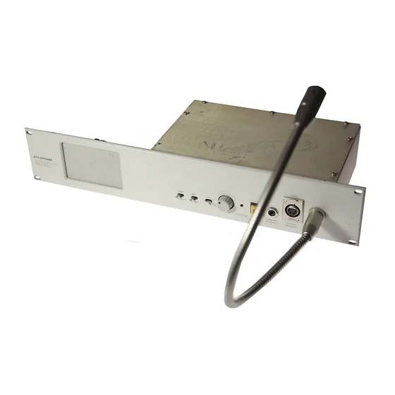
- Page 12 TECHNICAL DATA PACKAGE Model RMS300 TW Intercom System Rack Mount Speaker User Station Figure 3-1 Model R M S ' 3 O O Front Panel RTS Systems, Burbank, CA 91506 FSCM: 60572 TDP3504 Third Edition, Sept. 1989 Page...
-
Page 13: Section 3: Operation
Model RMS300 TW Intercom System Rack Mount Speaker User Station SECTION 3: OPERATION 3.1 Operating Controls (See Figure 3-1) Table 3-1 below lists the Model RMS300 operating controls. The reference numbers in Table 3-1 correspond to the circled numbers in Figure 3-1. Ref. - Page 14 Installation. Local Power Option. RMS300 and SPK308 The RMS300 and SPK300 can be powered from an external (local) powes supply of between 18 to option, a s supplied by RTS Systems uses a power supply assembly (RTS #9020-4425-OO), which is...
- Page 15 When system is constructed stations, it is essential that all channels are terminated with a 200 ohm system termination. System terminations include: An RTS Systems TW power supply*, A discrete 200 ohm resistor for each locally supplied channel, When application of a possible, a 10 microfarad/ ohm resistor for each See diagram below.
- Page 16 TECHNICAL DATA PACKAGE Model RMS300 SECTION DRAWINGS RTS Svstems Document Number Servicing Diagram, Light Signaling Circuit CC285 Servicing Diagram, Model RMS3001SPK300 Schematic Diagram, CC300, page 1 of 3 Schematic Diagram, CC300, page 2 of 3 Schematic Diagram, CC300, page 3 of 3 Wiring for External Microphones Wiring Diagram, pg.
- Page 18 FROM CHANNEL SELECT S W I T C H ( C H . l ) CH.1 CH.1 CH.2 CH.2 C H A S S I S GND FROM CHANNEL SELECT S W I T C H ( C H . 2 ) NOTE: U N I T MUST B E LOCAL POWERED...
- Page 21 D Y N BLACK M I C P R I M 0 #DM-1532 E Q U I V . PUSH-TO-TALK MICROPHONE SMALL M I C CALRAD # l o - 8 0 E Q U I V . OFF j 4 - P O ~ PUSH-TO-TALK MICROPHONE P 4 M...
- Page 22 OPTlOlclAL ELECTRET MIL & POWER OPf I O U RElYlOVE AND WleE JL T o LOLAL P.L.6. MOVEL.5 Wir14 53 I 5 h l ~ r &ED. A h J b W l E E OV'TlOd, C U T SLEEVE CUDS.
- Page 23 Y E L 2 VI O 2 GRY l I R E D MOUNTING XLR-4 OPTIONAL GOOSENECK ELECTRET MIC M IC A 3 m I T I O N TOGGLE SWITCH, C + K 7211 SPYABE 3CH OPTION* M3DIFY M E STANDARD CC-300 RC. BOARD .AS FOLLOWS: CUT TRACE INSIALL JUMPERS IN PLACE OF T5 ON RMS -300 SERIES ONLY.
- Page 24 ~PERKER Z - J p Z Z O % $ > a $ $ !iib$$ OPT\ONRL ELECTRET M\C JJT0 GOOSENECK MOUNTING XLR-4 'INPUT* "LOOP/EXT" AXR-3-31 AXR-3-32 C U T Sl.E€V€ W\U€ E N D S J Z (ZUI) MOMENTARY CARBON M \ C LIGHT BOARD...
- Page 25 REYIIIK)NII MICIIYMI( D A N Umovm R E V I S I ~ --..._Y-7tW_-84IZ:..--- LINE ( ~ c H ) CINE ( ~ C H ) SPEAKER CUT t SLEEVE WIRE ENDS CONN 5ARINK Fl ULRAD -455...
- Page 26 POSITICNJ < 7203SPYABE 1903-0025-00) ( RTS* GMSENECK 0PllokJAL ELECTRET M I L M I L YSTEMS INC.. HURBANK. C DUAL 5 D K A674MZIO 1407- 0022-00) (RT51L LIGHT BOARD HEADSET XLR-4-32 LOOP THRU MOMEtJTARY MIL MOT USED O N UUITS WITH CALL L ~ h n l OPTlotd SLEEVE ENDS.
- Page 27 REAR PANEL Fdi: INPUT R E M O V ~ PbZo&I?AMl O N : I - C ) O P I I JUMPERS AT U 3 PIUS 5,6<7. oPf10t.I cz(. I /50),clo(lmp~), cl0 (.ml/lCO), C Z B ( Z P ~ F > , FOR PROGRAM INPUT C107$ LIOB(Z.Z/~O), Kll4 PI3 (47<), ~23[150K), R4q(1oK), R51 (ICOY),...
- Page 28 Unmritched label information mic) see on drawing a&: On RMS300 unlts jumpers in place ofT5 On SPK300 UnftSm install jumper across S1. Install trensformerT5 (RTS #23060006W), and remove resistor R15. Gooseneck mic not Installed on SPKW units. Cut and sleeve wire ends.
- Page 29 SPSKER . C H 2 MOUNTILJG NUT LR-4 Goo5EtJECK oPTlohlAL E L E C T R E T M I L & SLEEVE RTS LINE (3CH) Rr5 LINE (2CH) LDNY LIGHT BOARD NEXTAU* DRAWNa APPLICATHIN DO NOT SCALE AEVlSlONS IPPAOVED DLJCR~PIION DATE SEE SHEET I...
- Page 30 GmSENECK OPTlOhlAL ELECTRET M I C MIL. AMACE SHOW^ 3 P T LOtJb CABLE AS MAK6 WIPE LAEELS "TBZ-1". DETAIL TAPE. PLUG "762-'L" "782-3" CISIN6 B p i I-IELvETIcA LIhHT, C L E M T H E INTO THE ' I S O " C q N N ~ T a R 6 h L Z PANEL.
- Page 31 RT5 UNE (2 CH) XLR-3-32 ELECTRET M\C C U T SLEEVE W\RE € N O S NOTES MYENSIOHS ARE INCHES T O C E ~ A H C ~ S ARE: REVISIONS ZONE OESCRlPrlON D l T E APPROVED SEE 5HEET I REMOVE OPTION.
- Page 32 REAR PANEL "PROGRAM IAI" fiOUNnNL1 IW- XLR- 6005Et.I.la~~ M I L - - - - RTLUM$'CHJ DUAL 5 0 K AUDIO (RTS 14.07-0022-00) MOMENTARY " ON" 05-115 M N l I40 SEE- SHEET orJc 7. FOR P R h W uw=z~~lcdav BALANCED MIL LT (S\OPTIO~~ W ~ E U tlJp~T...
Need help?
Do you have a question about the RMS300 and is the answer not in the manual?
Questions and answers