
Related Manuals for Avidsen Orane 510


Summary of Contents for Avidsen Orane 510
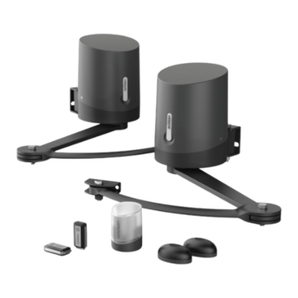
- Page 1 Orane 510 PIVOTING ARM MOTOR DRIVE KIT FOR 2-PANEL SWING GATES Ref. 114201 2,50M 250KG PORTAIL COMPATIBLE OPTION PAR BATTANT PAR BATTANT BATTANT AVEC TOUS TYPES SOLAIRE DE PORTAILS www.avidsen.com...
-
Page 2: Table Of Contents
CONTENTS A - SAFETY 3 - INSTALLING THE MOTOR DRIVE 3.1 - Installing the stops INSTRUCTIONS 3.2 - Assembling the pivoting arm 3.3 - Installing the motors - for opening 1 - OPERATING PRECAUTIONS towards the inside of the property 2 - INSTALLATION PRECAUTIONS 3.4 - Installing the motors - for opening 3 - MAINTENANCE AND CLEANING... - Page 3 D - BEGINNING 5 - PHOTOCELLS 5.1 - Obstacle detection OPERATION 6 - MANUAL MOVEMENT 1 - SETTINGS INTERFACE F - MAINTENANCE 2 - BASIC SETTINGS (MENU 1) AND UPKEEP 2.1 - Menu structure 2.2 - Photocell alignment procedure (optional) 1 - MAINTENANCE WORK 2.3 - Operating mode 2 - OPERATING INDICATORS...
-
Page 4: A - Safety Instructions
• Avidsen cannot be held liable for any use that does related to their development. not comply with the instructions in this manual and This automatic gate opening mechanism, and causes damage. -
Page 5: Maintenance And Cleaning
They • The company Avidsen cannot be held liable in could be swallowed by children or pets. May be fatal case of damage if installation is not conducted as if swallowed! In the event that a battery is swallowed, indicated in these instructions. -
Page 6: B - Product Description
B - PRODUCT DESCRIPTION 1 - KIT CONTENTS Main motor with electronic card M8 CHC – L30 screw Secondary motor M8 Washer Remote control M8 Spring washer Flashing light and screws M12 locknut Rear arm M10 nut Front arm M10 spring washer Pillar mounting bracket M10 washer Gate mounting bracket... -
Page 7: Equipment Required (Not Included)
B - PRODUCT DESCRIPTION 2 - EQUIPMENT REQUIRED (NOT INCLUDED) The tools and screws required for the installation must be in good condition and compliant with applicable safety standards. 1 spirit level 1 measuring 1 pencil 1 x 19mm box tape spanner 1 drill... -
Page 8: C - Installation
C - INSTALLATION 1. HAZARD ANALYSIS These maximum dimensions and weights are for an openwork-type gate and for use in an area 1.1. Regulation that is not very windy. For solid gates or a use in an area with significant wind speed, it is Installation of a motorised gate or a motor necessary to reduce the maximum values drive on an existing gate within the framework... -
Page 9: Subpanels
C - INSTALLATION After having checked that the gate to be motorised complies with the requirements given in this chapter and before beginning the installation, a hazard analysis of the installation must be conducted in order to eliminate all dangerous situations or to indicate them if they cannot be eliminated. 2. -
Page 10: Bottom Edges
C - INSTALLATION 2.2. Bottom edges Following installation, there may be a dangerous zone for toes between the bottom edge of the gate and the ground, as indicated in the following figure. In this case, this area must be removed leaving a working distance of minimum 50mm or maximum 5mm. Hazard Solution opening... -
Page 11: Prevention Of Other Hazards
C - INSTALLATION 2.4. Prevention of other hazards The body of a switch with no lock must be located in direct view of the driven part but away from moving parts. Unless it operates with a key, it must be installed at a minimum height of 1.5m and must not be accessible to the public. - Page 12 C - INSTALLATION Tip: Position the motor containing the electronic card on the post where the 230V electrical supply is located. If the 230V electrical supply is already located on the left post, the connections do not need to be reversed. If the electrical supply is located on the right post, it is sufficient to reverse the motor connection polarity in order to reverse the direction of rotation with respect to the assembly described in these instructions (normal mounting with motor and electronic card on the left).
-
Page 13: Assembling The Pivoting Arm
C - INSTALLATION Determine the opening angle of each panel based on the data in the following table. The opening angle may be different for each panel but must never be less than 40°. central stop Distance D opening up to (in mm) 90°... -
Page 14: Installing The Motors - For Opening Towards The Inside Of The Property
C - INSTALLATION 3.3 - Installing the motors - for opening towards the inside of the property • Place the mounting brackets against the posts, 14mm above the rigid part of the gate where the ends of the pivoting arms will be fastened. •... - Page 15 C - INSTALLATION • Depending on the maximum opening angle desired for the gate, the post bracket should be placed further from or nearer to the edge of the post (so that the motor does not prevent the gate from opening). For optimum motor operation, the distance X must be as small as possible.
- Page 16 C - INSTALLATION 12mm bit for plugs • Open the cover of the motors • Fasten the motors on the mounting brackets...
- Page 17 C - INSTALLATION Screw 11 Washer 18 Spring washer 17 Nut 16 • Assemble the pivoting arms and motors Washer 12 Washer 14 Screw 10...
- Page 18 C - INSTALLATION • Motor disengagement • Disengage the motors in order to manually manoeuvre the arms • Close the gate by pressing it firmly against the central stop. • Position the pivoting arms against the gate at a distance of 75cm and mark the location of the holes on the gate.
- Page 19 C - INSTALLATION • Remove the gate bracket from the arm in order to fasten it to the gate. • Use screws and nuts that are suitable for the gate material. • Reassemble the end of the arm and the gate bracket. Important: At this point in the installation, the motors are disengaged.
-
Page 20: Installing The Motors - For Opening Towards The Outside Of The Property
C - INSTALLATION 3.4 - Installing the motors - for opening towards the outside of the property • Place the mounting brackets against the posts, 14mm above the rigid part of the gate where the ends of the pivoting arms will be fastened. Inner side of the property •... - Page 21 C - INSTALLATION 115 mm 12mm bit for plugs • Open the cover of the motors...
- Page 22 C - INSTALLATION • Fasten the motors on the mounting brackets Screw 12 Nut 16 • Assemble the pivoting arms and motors Washer 14 Washer 20 Screw 13...
- Page 23 C - INSTALLATION • Motor disengagement • Disengage the motors in order to manually manoeuvre the arms. • Open the gate up to the side stops. • Turn the pivoting arm to press the gate bracket against the gate as far as possible from the hinges:...
- Page 24 C - INSTALLATION • Mark the holes for fastening the bracket on the gate. Important: The ends of the right arms should be at the middle of the rigid part of the gate so that the pivoting arms are completely horizontal. •...
- Page 25 C - INSTALLATION ž Or engage the motors: 4. FLASHING LIGHT INSTALLATION The flashing light must be fastened at the top of the post on which the switchgear is attached and must be visible both inside and outside. Only use the light provided in the kit (24 V - 2 W). The flashing light may be fastened on the wall with or without support.
- Page 26 C - INSTALLATION 5. ATTACHING THE SET OF PHOTOCELLS 5.1 - Opening inwards 1 set of photocells • Install the reception photocell (RX indicated on the back) on the motor post containing the electronic card. The surface of the posts must be perfectly flat in order to properly align the infrared beam of the photocells. •...
- Page 27 C - INSTALLATION 30cm min 60cm max Outer side of the property 10cm min 15cm max Perfect alignment View from above Inner side of the property 20 mm Outer side of the property Outer side of the property Outer side of the property...
-
Page 28: Opening Outwards
C - INSTALLATION 5.2 - Opening outwards 1 set of photocells • Install the reception photocell (RX indicated on the back) on the motor post containing the electronic card. The surface of the posts must be perfectly flat in order to properly align the infrared beam of the photocells. •... - Page 29 C - INSTALLATION 20 mm Inner side of the property Inner side of the property Inner side of the property 5.3 - 2 set of photocells (optional) For use when the gate is not visible. You must install a second set of photocells to prevent the gate from opening when an item (car, person, etc.) is behind the gate.
-
Page 30: Opening Inwards
C - INSTALLATION 30cm mini 60cm maxi pair 1 90° 90° 10 cm min 15 cm max pair 2 Opening inwards view from above pair 2 10 cm min 15 cm max 90° 90° pair 1 Opening outwards view from above... -
Page 31: Connections
C - INSTALLATION 6. CONNECTIONS • The cable run between must comply with applicable standards (NFC 15-100). • Either the cable is 80cm deep with red warning mesh, or the cable is run through a sheath. 230Vac Safety instructions • All electrical connections must be performed with the power switched off (safety switch in OFF position) and the battery disconnected. -
Page 32: Motors
C - INSTALLATION 6.2 - Motors For motor wiring without the electronic card, use a 2x1.5mm² cable and an insulating screw joint placed in the motor. Run the cable through the cable clamp and tighten • For inward opening with the motor mounted on the left post OR •... -
Page 33: Flashing Light
C - INSTALLATION 6.3 - Flashing light • Connect the flashing light wires to the terminal block as shown in the diagram below and reconnect the terminal block. • Use a 2x0.5mm² section cable, at least. • Maintain the connection polarity BAT TRANS PROG 6.4 - Photocells... -
Page 34: Control Parts (Optional)
C - INSTALLATION BAT TRANS • With 2 sets of photocells, remove the connector between GND and PHO photocell RX1 photocell TX1 NO COM NC photocell RX2 photocell TX1 NO COM NC 6.5 - Control parts (optional) BAT TRANS Note: These control parts must be normally open dry contacts. -
Page 35: Backup Battery (Optional)
C - INSTALLATION 6.6 - Backup battery (optional) It is possible to connect a backup battery to perform some manoeuvres in the event of power failure. • Type of battery: NiMH • Battery voltage: 24 V • Configuration: 20xAAA / 800mAh •... -
Page 36: D - Beginning Operation
D - BEGINNING OPERATION 1. SETTINGS INTERFACE 2. BASIC SETTINGS (MENU 1) Indicators 2.1. Menu structure After it is switched on, all LEDs will be turned off except the green LED • If the green LED is off, the card is on standby mode. - Page 37 D - BEGINNING OPERATION...
-
Page 38: Photocell Alignment Procedure (Optional)
D - BEGINNING OPERATION 2.2. Photocell alignment procedure (optional) open for a certain time (adjustable time, see “Time delay”), then closes automatically. The electronic card of this motorised gate is on Unlike the automatic closing mode: standby after 1 minute with no action. •... -
Page 39: Motor Force
D - BEGINNING OPERATION and confirm with the OK button. All the LEDs will switch on and off to confirm the operation. 15 s NOTE: if the force setting is changed, self-learning 30 s must be repeated. 45 s 60 s 2.6. - Page 40 D - BEGINNING OPERATION ajar) before starting the self-learning procedure. codes: : LED off SAFETY : LED on Make sure that there is no one in the gate : Flashing LED light movement area during the entire start-up period Make sure not to confuse the self-learning and the entire test period.
-
Page 41: Programming Remote Controls
D - BEGINNING OPERATION with the electronic card. In phase 1, panel M2 did • There is a fault in the motor. not reach a stop after • The section of the motor cable is too weak. opening for 60s or cable ž... -
Page 42: Advanced Settings
D - BEGINNING OPERATION control button for memorisation. • If the red LEDs all turn on for 1 second, this means that memorisation is successful. • If the red LEDs all flash 3 times, this means that the system has waited for more than 10 seconds without receiving valid information. -
Page 43: Advanced Settings Menu (Menu 2)
D - BEGINNING OPERATION once, L1 will turn on and you will be in menu 1 to open. The default level is 3, at which the gate takes about 4 seconds to open. It may be useful to (basic settings). •... - Page 44 D - BEGINNING OPERATION learning must be repeated. 3.2.3. Type of gate 3.2.2. Photocell mode To operate the electronic card on a single-panel gate, this setting must be changed. By default, this The photocells are active when the panels close value is set to 0 (two-panel gate mode).
-
Page 45: Advanced Settings Menu (Menu 3)
D - BEGINNING OPERATION obstacle detection tolerance must be increased. 3.3.1. Panel movement time difference To adjust this tolerance level, follow the In general, on closing, one gate panel closes over procedure below the other. This panel is controlled by the motor •... - Page 46 D - BEGINNING OPERATION 3.3.2 - Pre-flashing time The flashing light is an important safety component. It starts when a command to set the gate in motion is received by the electronic card. The gate is set in motion around one second after a command is received.
-
Page 47: E - Use
Avidsen cannot be held liable for any installation or use that does not comply with the instructions 3. TYPE OF COMMAND and causes damage. It is essential to read the... -
Page 48: Automatic Closing" Mode
E - USE • Activate the complete (or partial) opening • The flashing light will stop flashing and the manoeuvre command. will be complete. • The flashing light will flash (1 flash per second). • 1 second later, panel M1 starts opening. At any time, you can stop the gate’s movement •... -
Page 49: Obstacle Detection
E - USE Warning: 5.1. Obstacle detection When the motors are disengaged, the gate may be set in motion by the wind or an external push. It is During their movement, the panels may encounter therefore important to be careful or block the gate to an obstacle. -
Page 50: F - Maintenance And Upkeep
F - MAINTENANCE AND UPKEEP 1. MAINTENANCE WORK Maintenance work must be carried out by the installer or a qualified individual to guarantee the installation’s operation and safety. The number of maintenance and upkeep operations must be proportional to the frequency the motorised gate is used. -
Page 51: Operating Indicators
F - MAINTENANCE AND UPKEEP 2. OPERATING INDICATORS This system has two operating indicators: the battery charge level (optional) and the event log. historique des événements Code 4 – Code 3 du plus récent OK 3s – au plus efface historique ancien Code 2 PROG... -
Page 52: Manual Control
F - MAINTENANCE AND UPKEEP Motor M2 is not connected or incorrectly connected (contact failure). Check connections. The maximum operating time has been reached (a motor is idle and the stop has not been reached?). Check that the motor is engaged. Panel M1 closed before panel M2. -
Page 53: Total Reset
F - MAINTENANCE AND UPKEEP In addition, in this mode, LEDs L1 and L2 are used to test the status of the photocell inputs (PHO) and wired control (2B): If photocells are connected, LED L1 will be on if the infrared beam is unobstructed. -
Page 54: Replacing The Power Fuse
F - MAINTENANCE AND UPKEEP 2.5. Replacing the power fuse • With a Philips screwdriver, remove the 3 screws behind the remote control. • Switch the motor drive off. • Use a 250V 5A time-delay fuse • Open the remote control and remove the batteries. -
Page 55: Compatible Accessories
Solar kit 2. TECHNICAL CHARACTERISTICS The technical characteristics are provided as an indication only and for a temperature of +20°C. The avidsen company reserves the right to modify these characteristics at any time, while under all circumstances guaranteeing these products’ smooth operation and the type of use intended, with a view to improving these products. - Page 56 G - TECHNICAL AND LEGAL INFORMATION Consumption at rated strength 3 A Assigned operating duration 10 cycles per hour Maximum number of cycles 100 cycles per day Operating temperature -20°C/ +60°C Protection rating IP44 FLASHING LIGHT LED lighting 8W max, flashing managed Type by the electronic card Power supply...
-
Page 57: Warranty
G - TECHNICAL AND LEGAL INFORMATION Maximum assigned power 0.7W for the pair - 1 output with normally closed dry contact (COM/NC) Output - 1 output with normally open dry contact (COM/NO) Transmission angle/Reception angle 10° approx. / 10° approx. 15m maximum (range may be reduced due to weather Range disruption) -
Page 58: Product Returns/After-Sales Service
If, despite the care we have taken in designing and manufacturing your product, it needs to be returned to our customer service centre. Avidsen undertakes to keep a stock of spare parts for this product throughout the contractual warranty period. - Page 60 Avidsen 19 avenue Marcel Dassault - ZAC des Deux Lions 37200 Tours - France...
Need help?
Do you have a question about the Orane 510 and is the answer not in the manual?
Questions and answers