
Related Manuals for Avidsen 114461


Summary of Contents for Avidsen 114461
- Page 1 TECHNICAL SUPPORT WARRANTY OREA CONNECT CONNECTED MOTOR DRIVE KIT For sliding gates Ref.114461 24 V SWING 500KG COMPATIBLE WITH ALL COMPATIBLE WITH GATE TYPES OF GATES AVIDSEN HOME www.avidsen.com...
-
Page 2: Table Of Contents
CONNECTED MOTOR DRIVE KIT CONTENTS A - SAFETY INSTRUCTIONS 11.4 - Emergency stop parts 11.5 - Solar power kit 1 - OPERATING PRECAUTIONS D - BEGINNING OPERATION 2 - INSTALLATION PRECAUTIONS 3 - MAINTENANCE AND CLEANING 1 - SETTINGS INTERFACE 4 - RECYCLING 2 - QUICK SETTINGS B - PRODUCT DESCRIPTION... - Page 3 F - MAINTENANCE AND 4.2 - Connecting the contactor UPKEEP 4.3 - Usage via the application 4.4 - Using the product with Google Home 36 1 - MAINTENANCE WORK 4.4.1 - If you have an Android smartphone with Google Assistant 2 - OPERATING INDICATORS 4.5 - Using the product with Amazon Alexa 37 3 - BATTERY VOLTAGE (FOR OPTIONAL SOLAR...
-
Page 4: A - Safety Instructions
Avidsen cannot be held liable for any use that does related to their development. not comply with the instructions in this manual and This automatic gate opening mechanism, and causes damage. -
Page 5: Maintenance And Cleaning
This logo denotes that devices no longer in reach of children. use should not be disposed of as The Avidsen company shall not be responsible household waste. They are likely to contain in case of damage if installation is not... -
Page 6: B - Product Description
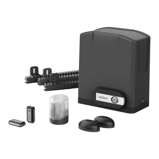
CONNECTED MOTOR DRIVE KIT B - PRODUCT DESCRIPTION 1 - CONTENTS OF THE KIT x 12 x 12 24 V geared motor Ø8 spring washer 50cm rack and screws Photocells and their screws Flashing light and screws Disengagement label Remote control Installation template Release key Backup fuses... -
Page 7: C - Installation
CONNECTED MOTOR DRIVE KIT C - INSTALLATION HAZARD ANALYSIS SPECIFICATIONS OF THE GATE TO MOTORISE REGULATION This motor drive can automate sliding gates up to 8m Installation of a motorised gate or a motor drive on long and 2.20m high and weighing 500kg. an existing gate within the framework of “Residential”... -
Page 8: Safety Rules
CONNECTED MOTOR DRIVE KIT C - INSTALLATION Grille, net or safety edge Upper runner Clearance zone Rail Open end stop Close end stop SAFETY RULES The actual opening of a gate may create dangerous situations for people, goods and vehicles in the vicinity that by nature, cannot always be avoided by design. - Page 9 CONNECTED MOTOR DRIVE KIT C - INSTALLATION Solution with photocells: swing post post rail reception photocell (RX) transmission photocell (TX) geared motor rack view from above To avoid any risk of confinement in the gate clearance zone, the safety distances given in the diagram below must be observed.
-
Page 10: Attaching Components
CONNECTED MOTOR DRIVE KIT C - INSTALLATION swing protector < 8mm rack Between the bars of an openwork gate and the post If the gate is openwork type, there is a risk of shearing between the gate bars and the post when the gate is opening. -
Page 11: Attaching The Geared Motor
CONNECTED MOTOR DRIVE KIT C - INSTALLATION Installation of different components Note: from now until the end of this guide: • Left to right opening will be referred to as “LR opening”. Flashing light Attachment: page 15 Reception photocell Attachment: page 16 Transmission photocell Attachment: page 16 opening direction... - Page 12 CONNECTED MOTOR DRIVE KIT C - INSTALLATION Post Post 15mm Gate Gate 15mm 5.5 cm 5.5 cm Post Template Template Foundation Foundation view from above The cable run between must comply with applicable standards (NFC 15-100). Either the cable is 80cm deep with red warning mesh, or the cable is run through a sheath.
-
Page 13: Attaching The Rack
CONNECTED MOTOR DRIVE KIT C - INSTALLATION When the motor is horizontal, tighten the locknuts to block the clamp nut then tighten the clamp nuts to keep the motor in position. 2.2 - ATTACHING THE RACK In order to manually manoeuvre the gate during rack installation, the geared motor must be disengaged as follows: •... -
Page 14: Attaching The Flashing Light
CONNECTED MOTOR DRIVE KIT C - INSTALLATION • Using a ruler and spirit level, assemble and attach the remaining rack components to the gate. Once attached, all components must be perfectly aligned and level. ruler level 10mm 3 - INSTALLING THE FLASHING LIGHT The flashing light must be attached to the top of the post on which the switchgear is mounted, and it must be visible from both the inside and the outside. - Page 15 CONNECTED MOTOR DRIVE KIT C - INSTALLATION...
-
Page 16: Attaching The Set Of Photocells
CONNECTED MOTOR DRIVE KIT C - INSTALLATION 4 - ATTACHING THE SET OF PHOTOCELLS Important notes: • The photocells must be perfectly aligned and parallel to each other. • The reception photocells (RX is indicated at the back) must be installed at the same side of the gate as the geared motor. -
Page 17: Connections
CONNECTED MOTOR DRIVE KIT C - INSTALLATION 5 - CONNECTIONS Safety instructions: All electrical connections must be performed with the power switched off (safety switch in OFF position). These connections must be made by a qualified electrician. Typical connection flashing light wired control part (contactor, motor interphone, etc.) -
Page 18: Electronic Control Card
CONNECTED MOTOR DRIVE KIT C - INSTALLATION 6 - ELECTRONIC CONTROL CARD For ease of connection, all terminal blocks are removable. battery transfo connection red LED connection green LED fuse fuse settings transfo battery buttons gate opening pedestrian antenna sensor motor photocells light... -
Page 19: Photocells
CONNECTED MOTOR DRIVE KIT C - INSTALLATION 9 - PHOTOCELLS Warning: Make the photocell connections when the actuator power is switched off. • Disconnect the removable terminal block, connect the photocell wires to the terminal block as shown in the diagram below and then reconnect the terminal block. -
Page 20: Optional Accessories
CONNECTED MOTOR DRIVE KIT C - INSTALLATION • Install the magnet for state feedback of the gate from the application. • Put the gate in closed position. • Attach the passive magnet to the gate. Install the magnet bracket on the ground, leaving a gap of no more than 13mm between the magnets. -
Page 21: Additional Photocells
CONNECTED MOTOR DRIVE KIT C - INSTALLATION 11.1 - ADDITIONAL PHOTOCELLS For use when the gate is not visible. You must install a second set of photocells to prevent the gate from opening when an item (car, person, etc.) is behind the gate. Installation The photocells must be perfectly aligned and parallel to each other. -
Page 22: Additional Control Parts
CONNECTED MOTOR DRIVE KIT C - INSTALLATION If using the STOP input, you must remove the connector between STOP and GND Photocell Photocell Photocell Photocell 11.2 - ADDITIONAL CONTROL PARTS Gate control Pedestrian control push button push button interphone output, interphone output, key contact key contact... -
Page 23: Key Selector
CONNECTED MOTOR DRIVE KIT C - INSTALLATION 11.3 - KEY SELECTOR partial opening complete opening 11.4 - EMERGENCY STOP PARTS The input for emergency stop parts is normally closed dry contact type. If no emergency stop part is installed, you must leave the connector closing the contact between STOP and GND. Examples of emergency stop parts: •... -
Page 24: Solar Power Kit
CONNECTED MOTOR DRIVE KIT C - INSTALLATION 11.5 - SOLAR POWER KIT Note: the motor drive can be powered by a solar kit, however the connected module will not function. To do this, there is a battery and solar panel kit that can be connected instead of the 230V supply.Note: It is essential to disconnect the 230V power supply when the solar power supply kit is connected. -
Page 25: D - Beginning Operation
CONNECTED MOTOR DRIVE KIT D - BEGINNING OPERATION 1 - SETTINGS INTERFACE All LEDs are turned off except the green LED • If the green LED is not lit, press PROG. Indicators • Lit up green LEDs are an error code (see paragraph “Event history and error code”). - Page 26 CONNECTED MOTOR DRIVE KIT D - BEGINNING OPERATION...
-
Page 27: Photocell Alignment Procedure
CONNECTED MOTOR DRIVE KIT D - BEGINNING OPERATION 2.2 - PHOTOCELL ALIGNMENT PROCEDURE procedure may be interrupted at any time by pressing SET. The electronic card of this motorised gate is on standby after 1 minute with no action. On standby, Self-learning procedure the photocells no longer have power. -
Page 28: Programming Remote Controls
CONNECTED MOTOR DRIVE KIT D - BEGINNING OPERATION Meaning The motor has run for 60 seconds on closing without the gate finding a stop; this is not normal. The motor has run for less than 3 seconds to open the gate; this is not normal. Can the gate open and close freely? The motor has run for less than 3 seconds to close the gate;... -
Page 29: Deleting All Remote Controls
CONNECTED MOTOR DRIVE KIT D - BEGINNING OPERATION 2.4.3 - DELETING ALL REMOTE CONTROLS 2.6 - OPERATING MODE This automatic gate opening mechanism has 3 To deprogram all the remote control buttons operating modes. learnt, follow the procedure below • Press “–” for 3 seconds and L1 will switch on. Semi-automatic mode (mode 1) (default) •... -
Page 30: Time Delay
CONNECTED MOTOR DRIVE KIT D - BEGINNING OPERATION To choose the operating mode, set a value 2.7 - TIME DELAY from 1 to 3. Follow the procedure below The time delay is the time during which the gate remains open before closing automatically (if •... -
Page 31: Speed
CONNECTED MOTOR DRIVE KIT D - BEGINNING OPERATION 3.2.1 - SPEED You can adjust the speed by a value of 0 to 5. To adjust this value, follow this procedure • Press PROG for 3 seconds › L0 will flash once and L1 will turn on. -
Page 32: Photocell Self-Test (Optional)
CONNECTED MOTOR DRIVE KIT D - BEGINNING OPERATION To adjust this value, follow this procedure To activate or deactivate this function, follow • Press PROG for 3 seconds › L0 will flash once the procedure below and L1 will turn on. •... -
Page 33: Homegate Connected Module Start-Up
CREATING AN ACCOUNT Once the contactor is connected, follow the instructions below to pair it. Download the Avidsen Home app from the Android Play Store or Apple App Store. Launch the app and log in if you already have an account. -
Page 34: Connecting The Contactor
CONNECTED MOTOR DRIVE KIT D - BEGINNING OPERATION Make sure the contactor is connected and its indicator light is flashing. Otherwise, press the reset button for 5s so that the blue indicator light starts flashing. Select your 2.4GHz WiFi network (note: your smartphone must be connected to the WiFi network to which the plug will be connected), enter your network password and press suivant (next). -
Page 35: Usage Via The Application
GHz - WPA/WPA2 networks. Not compatible your app. with 5 GHz WiFi or with WEP encryption. Please You can now control your Avidsen contactor from check the WiFi settings of your router or contact your smartphone. your Internet service provider if you experience You can rename it by clicking on the small pencil to connection difficulties. -
Page 36: Using The Product With Google Home
D - BEGINNING OPERATION 4.4 - USING THE PRODUCT WITH GOOGLE HOME Gate position status (display when in Note: the name you give your Avidsen Home operation) in relation to the magnets devices is the one that will be recognised by Google Assistant. -
Page 37: If You Have An Android Smartphone With Google Assistant
- In the Amazon Alexa app, press the menu at the top left and select Skills et Jeux (Skills and Games). - Search for Avidsen Home in the list of skills or use Recherche (Search) at the top right. - Select the Avidsen Home Skill and activate for use. -
Page 38: Scenario And Automation
Alexa, contact Amazon support. 4.6 - SCENARIO AND AUTOMATION 4.6.1 - SCENARIO The scenario system in the Avidsen Home app allows you to group actions that will be triggered on demand, by clicking on a single button on your Name your scenario, then click on to set the smartphone. -
Page 39: Creating An Automation
The automation system in the Avidsen Home app allows you to group devices and actions which will be triggered automatically by the action of another device or a condition (temperature, time, etc.). - Page 40 CONNECTED MOTOR DRIVE KIT D - BEGINNING OPERATION After selecting the condition type, choose the Go back conditions themselves: Save automation Change the automation name You can change the background image if you wish Selection of condition type Selection of conditions to be met for actions to be executed Selection of actions to be executed Selection of the automation validity time...
-
Page 41: Programming The "Gate Opening" Automation
CONNECTED MOTOR DRIVE KIT D - BEGINNING OPERATION The following part is related to the actions that will be The last setting allows you to define a time slot during triggered by the conditions: the day, if necessary, during which to authorise the automation launch: Once all these settings have been confirmed, you can save your automation at the top right... - Page 42 CONNECTED MOTOR DRIVE KIT D - BEGINNING OPERATION The first setting is stored. Now you must program the time. Click on +. Select the opening time. Slide your finger up or down the time column in the minute column. The time configured will appear between the two parallel lines.
- Page 43 CONNECTED MOTOR DRIVE KIT D - BEGINNING OPERATION Rename your scenario at your convenience (in our Next you need to determine the action to be example: “GATE OPENING”) performed. Once all parameters have been set, click on Save. If you wish to access the details or delete it, click on the “...”...
-
Page 44: E - Use
Full opening command remove all hazardous situations. Avidsen cannot be held liable for any installation or use that does not comply with the instructions and causes damage. Partial opening command (opening 1m20) -
Page 45: Automatic Closing" Mode
CONNECTED MOTOR DRIVE KIT E - USE 2.2.2 - “AUTOMATIC CLOSING” MODE • If, after 30 seconds, the emergency stop part is still activated, the flashing light will stop and the Description of operation from the closed gate electronic card will go on standby. position: •... -
Page 46: Manual Movement
CONNECTED MOTOR DRIVE KIT E - USE 2.6 - MANUAL MOVEMENT 2.8 - MOTOR ENGAGEMENT To be able to manoeuvre the gate manually, you • Return the override lever to the initial position. must disengage the geared motor. • Turn the key anticlockwise. Warning: •... -
Page 47: F - Maintenance And Upkeep
CONNECTED MOTOR DRIVE KIT F - MAINTENANCE AND UPKEEP 1 - MAINTENANCE WORK Maintenance work must be carried out by the installer or a qualified individual to guarantee the installation’s operation and safety. The number of maintenance and upkeep operations must be proportional to the frequency the motorised gate is used. -
Page 48: Anomaly Guide
CONNECTED MOTOR DRIVE KIT F - MAINTENANCE AND UPKEEP 4 - ANOMALY GUIDE TYPE OF FAULT PROBABLE CAUSE WHAT YOU SHOULD DO When activating the opening No 230-volt power supply Switch the power back on command, the gate does not Emergency stop pressed and/or Connect the STOP terminals to the move and the motor does not... - Page 49 CONNECTED MOTOR DRIVE KIT F - MAINTENANCE AND UPKEEP Meaning Type The emergency stop input has been activated A card power supply fault has been detected. It may be a short-circuit on the +12V output. Check the connections. An obstacle has been detected in the gate when opening. The photocell beam has been cut Photocell self-test failure.
-
Page 50: Manual Control
CONNECTED MOTOR DRIVE KIT F - MAINTENANCE AND UPKEEP 4.1 - MANUAL CONTROL You can manoeuvre the gate with no programming, for example during installation, to check the opening direction is correct. • To enter manual mode, press “SET” for 3 seconds and LED L3 will flash. -
Page 51: G - Technical And Legal Information
The technical characteristics are provided as an indication only and for a temperature of +20°C. The company Avidsen reserves the right to modify these characteristics at any time, while under all circumstances guaranteeing these products’ smooth operation and the type of use intended, in an aim to improve these products. - Page 52 CONNECTED MOTOR DRIVE KIT G - TECHNICAL AND LEGAL INFORMATION REMOTE CONTROL Type: OOK AM modulation. 16-bit Rolling code encoder Type (i.e. 65,536 possible combinations) Frequency 433.92MHz Power supply 3V, CR2032 battery Touch-sensitive 4 keys Radiated power < 10mW Battery life 2 years at a rate of 10 x 2s uses per day Operating temperature -20°C/+60°C...
- Page 53 CONNECTED MOTOR DRIVE KIT G - TECHNICAL AND LEGAL INFORMATION HOMEGATE MODULE Max. power 200W Features Opens gates and garage doors Wired Connection 1 output Cable cross-section Up to 1.5mm Indoors and outdoors Operating temperature -10°C/+50°C Storage temperature -20°C/+70°C Power supply 230 VAC/50 Hz Average consumption <...
-
Page 54: Warranty
• The parts of this product must not be opened http://www.avidsen.com/nos-services or repaired by any persons not employed by Avidsen. Avidsen undertakes to keep a stock of spare parts • The warranty will be void if the device is tampered for this product throughout the contractual warranty with. -
Page 55: Declaration Of Conformity
EN 301489-1 V2.2.3 EN 301489-3 V2.1.1 Avidsen declares, under its sole responsibility, that the remote control included in the 114461 kit complies with the applicable Union harmonisation legislation. Its conformity has been assessed pursuant to the applicable standards in force: - Directive RED 2014/53/EU EN 300 220-1 V3.1.1... - Page 56 Avidsen 19 avenue Marcel Dassault 37200 Tours - France...
Need help?
Do you have a question about the 114461 and is the answer not in the manual?
Questions and answers