Table of Contents
Advertisement
TECHNICAL
SUPPORT
3
WARRANTY
Styrka 310
TELESCOPIC MOTOR DRIVE KIT
FOR 2-PANEL SWING GATES
Ref.114170
EN
H
KG
L
24V
OPENING
2.50M
2.20M
150KG
COMPATIBLE WITH
SOLAR
SMARTPHONE
PHOTOCELL
PANEL
PER PANEL
MAXIMUM
PER PANEL
WITH ALL TYPES
OPTION
COMPATIBLE
OPTION
OF OPENWORK GATES
OPTION
www.avidsen.com
V4
Advertisement
Table of Contents

Related Manuals for Avidsen Styrka 310


Summary of Contents for Avidsen Styrka 310
- Page 1 TECHNICAL SUPPORT WARRANTY Styrka 310 TELESCOPIC MOTOR DRIVE KIT FOR 2-PANEL SWING GATES Ref.114170 OPENING 2.50M 2.20M 150KG COMPATIBLE WITH SOLAR SMARTPHONE PHOTOCELL PANEL PER PANEL MAXIMUM PER PANEL WITH ALL TYPES OPTION COMPATIBLE OPTION OF OPENWORK GATES OPTION www.avidsen.com...
-
Page 2: Table Of Contents
CONTENTS A - SAFETY 7 - CONNECTIONS 7.1 - The mains electricity INSTRUCTIONS 7.2 - Telescopic motors 7.3 - Flashing light 1 - OPERATING PRECAUTIONS 7.4 - Photocells (optional) 7.5 - Control parts (optional) 2 - INSTALLATION PRECAUTIONS 7.6 - Backup battery (optional) 3 - MAINTENANCE AND CLEANING 7.7 - Solar power kit (optional) 4 - RECYCLING... - Page 3 G - TECHNICAL 3.2.3 - Type of gate 3.2.4 - Stop tolerance AND LEGAL 3.3 - Advanced settings menu (menu 3) 3.3.1 - Panel movement time interval INFORMATION 3.3.2 - Pre-flashing time 1 - TECHNICAL CHARACTERISTICS E - USE 2 - WARRANTY 3 - HELP AND ADVICE 1 - WARNINGS 4 - PRODUCT RETURNS/AFTER SALES...
-
Page 4: A - Safety Instructions
Avidsen cannot be held liable for any use that does This automatic gate opening mechanism, and not comply with the instructions in this manual and its manual, were designed to enable a gate to be causes damage. -
Page 5: Maintenance And Cleaning
The Avidsen company shall not be responsible in case of damage if installation is not conducted as indicated in these instructions. Pour en savoir plus : 3 - MAINTENANCE AND CLEANING www.quefairedemesdechets.fr... -
Page 6: B - Product Description
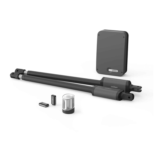
B - PRODUCT DESCRIPTION 1 - CONTENTS OF THE KIT Telescopic motors 24V Spacer Switchgear Elastic pin Post mounting bracket Remote control Gate mounting bracket Flashing light Clevis pins 2 - EQUIPMENT REQUIRED (NOT INCLUDED) The tools and screws required for the installation must be in good condition and compliant with applicable safety standards. -
Page 7: C - Installation
C - INSTALLATION 1 - HAZARD ANALYSIS 1.2 - Specifications of the gate to motorise 1.1 - Regulations This motor drive can automate swing gates up to Installation of a motorised gate or a motor drive on 2.50m wide and 2.20m high and weighing 150kg. an existing gate within the framework of “Residential”... -
Page 8: Safety Rules
C - INSTALLATION 1.4 - Safety rules The actual opening of a gate may create dangerous situations for people, goods and vehicles in the vicinity that by nature, cannot always be avoided by design. The possible hazards depend on the state of the gate, the manner in which it is used and the installation site. After having checked that the gate to be motorised complies with the requirements given in this chapter and before beginning the installation, a hazard analysis of the installation must be conducted in order to eliminate all dangerous situations or to indicate them if they cannot be eliminated. -
Page 9: Installing The Motors
C - INSTALLATION hazard solution opening opening opening 50mm minimum minimum hazardous zone view in profile Between the panels and the fixed parts close to each other Depending on the configuration of the site where the motorised gate is installed, there may be confinement areas between the panels in open position and the fixed parts close to them. - Page 10 C - INSTALLATION • The use of stops is mandatory (not provided) This gate motor drive is a self-locking motorisation system. Your 2-panel gate must be equipped with a central stop and side stops (not included). The (central and side) stops must stop the gate without locking it. In other words, any mechanical lock (or latch) and any tilting shoe base or stopper must be removed.
- Page 11 C - INSTALLATION Determine the opening angle of each panel based on the data in the following table. The opening angle may be different for each panel but must never be less than 40°. central stop Distance D opening up to (in mm) 90°...
- Page 12 C - INSTALLATION Attaching the post mounting bracket Mount the motors to a rigid and reinforced part of the gate (e.g. the frame or the crossbar). Mount them as low as possible for aesthetic and technical reasons. CORRECT IDEAL The instructions below describe installation of the left motor; to install the right motor, repeat the process while respecting the symmetry.
- Page 13 C - INSTALLATION Please note: there will be significant force on the mounting bracket when the motor drive is running. We recommend sealing threaded rods at least 15 cm in length. If the post is made of metal, we recommend welding or passing the threaded rods through to secure them with self-locking nuts.
- Page 14 C - INSTALLATION Positioning of the bracket on the gate To position the motor on the gate, the motor rod must be retracted 20mm from its fully extended position. If this distance is not strictly observed, the motors may experience operating problems that are not covered by the product warranty.
-
Page 15: Installing The Switchgear
C - INSTALLATION 4 - INSTALLING THE SWITCHGEAR The switchgear must be mounted to the post where the 230Vac power comes from. • To ensure proper operation of the motorisation, the length of the motor cables must not exceed 8 m per motor. -
Page 16: Installing The Set Of Photocells (Optional)
C - INSTALLATION 6 - INSTALLING THE SET OF PHOTOCELLS (OPTIONAL) 1 set of photocells • Install the reception photocell (RX indicated at the back) of the same side of the gate as the switchgear. The surface of the posts must be perfectly flat in order to properly align the infrared beam of the photocells. •... - Page 17 C - INSTALLATION 30cm 60cm Outer side of the property 10cm min 15cm max perfect alignment view from above Inner side of the property 20mm Outer side of the property Outer side of the property Outer side of the property...
-
Page 18: Connections
C - INSTALLATION 7 - CONNECTIONS • The cable run between must comply with applicable standards (NFC 15-100). • Either the cable is 80 cm deep with red warning mesh, or the cable is run through a sheath. vers 230V Safety instructions •... -
Page 19: The Mains Electricity
C - INSTALLATION 7.1 - THE MAINS ELECTRICITY Important notes: • The electrical line may only be used to power the gate motor drive. It must be protected by a fuse or circuit breaker (6A min., 16A max.) and a differential device (30mA). It must be compliant with the applicable electrical safety standards. -
Page 20: Telescopic Motors
C - INSTALLATION 7.2 - TELESCOPIC MOTORS For motor wiring on the electronic card, use a 2x1.5mm² cable. Run the cable through the cable clamp and tighten • For opening towards the inside BAT TRANS PROG The motor that opens first must be connected to the M1 output of the electronic card. -
Page 21: Photocells (Optional)
C - INSTALLATION 7.4 - PHOTOCELLS (OPTIONAL) BAT TRANS • If there are no photocells, leave the connector between GND and PHO. • With one set of photocells, remove the connector between GND and PHO. BAT TRANS photocell RX1 photocell TX1 NO COM NC •... -
Page 22: Backup Battery (Optional)
C - INSTALLATION 7.6 - BACKUP BATTERY (OPTIONAL) It is possible to connect a backup battery to perform some manoeuvres in the event of power failure. • Type of battery: NiMH • Battery voltage: 24V • Configuration: 20xAAA / 800mAh •... -
Page 23: D - Beginning Operation
D - BEGINNING OPERATION 1 - SETTINGS INTERFACE 2 - BASIC SETTINGS (MENU 1) Indicators 2.1 - MENU STRUCTURE After it is switched on, all LEDs will be turned off except the green LED • If the green LED is off, the card is on standby mode. - Page 24 D - BEGINNING OPERATION...
-
Page 25: Photocell Alignment Procedure (Optional)
D - BEGINNING OPERATION 2.2 - PHOTOCELL ALIGNMENT PROCEDURE • Closed gate: pressing and releasing the gate (OPTIONAL) command once opens the gate, which remains open for a certain time (adjustable time, see “Time The electronic card of this motorised gate is on delay”), then closes automatically. -
Page 26: Motor Force
D - BEGINNING OPERATION seconds and is 30 seconds by default. NOTE: if the force setting is changed, self-learning must be repeated. 2.6 - SPEED 15 s 30 s You can adjust the speed by a value of 0 to 4. The default speed is 3. - Page 27 D - BEGINNING OPERATION PROG and then + (not at the same time). The panels should open. If a panel closes, reverse the Below is a table indicating the self-learning error + and - on the card. codes: To exit manual control mode, do a short press on : LED off PROG and - at the same time.
-
Page 28: Programming Remote Controls
D - BEGINNING OPERATION means that memorisation is successful. In phase 1, panel M2 did • If the red LEDs all flash 3 times, this means not reach a stop after that the system has waited for more than 10 opening for 60s or cable seconds without receiving valid information. -
Page 29: Deleting All Remote Controls
D - BEGINNING OPERATION 2.8.3 - DELETING ALL REMOTE CONTROLS To deprogram all the remote control buttons learnt, follow the procedure below • Press “–” for 3 seconds and L1 will switch on. • Press “+” twice and L1 will turn off and L3 will turn •... -
Page 30: Advanced Settings Menu (Menu 2)
D - BEGINNING OPERATION • Press PROG again for 3 seconds. L0 will flash twice, L1 will turn on and you will be in menu 2 (advanced settings). • Press PROG again for 3 seconds. L0 will flash three times, L1 will turn on and you will be in menu 3 (advanced settings). -
Page 31: Type Of Gate
D - BEGINNING OPERATION activate side gate mode, then OK to confirm. All pair 1 LEDs will turn on and off to confirm the operation. • If L1 is on, side gate mode is activated. Press “–” to activate gate mode, then OK to confirm. All LEDs will turn on and off to confirm the operation. -
Page 32: Advanced Settings Menu (Menu 3)
D - BEGINNING OPERATION • Use the “+” and “-” buttons to change this value 3.3 - ADVANCED SETTINGS MENU (MENU 3 (see table below). • Press OK to confirm this value. All the LEDs will turn on and off to confirm the operation. Décalage fermeture –... - Page 33 D - BEGINNING OPERATION 3.3.2 - PRE-FLASHING TIME The flashing light is an important safety component. It starts when a command to set the gate in motion is received by the electronic card. The gate is set in motion around one second after a command is received.
-
Page 34: E - Use
3 - TYPE OF COMMAND Avidsen cannot be held liable for any installation or There are two types of command to manoeuvre the use that does not comply with the instructions and gate: causes damage. -
Page 35: Semi-Automatic Closing" Mode
E - USE 4.1 - “SEMI-AUTOMATIC CLOSING” MODE At any time, you can stop the gate’s movement by activating a command (total or partial). If you activate Description of operation from the closed gate the gate control again, the gate will start in the opposite direction. -
Page 36: Obstacle Detection
E - USE 5.1 - OBSTACLE DETECTION During their movement, the panels may encounter an obstacle. • For safety purposes, if the motors are under too much strain (the force is adjustable; see “Motor Force” in the settings), the gate stops and releases the pressure and the flashing light emits double flashes for 30 seconds unless a command is activated. -
Page 37: Optional Accessories
E - USE 7 - OPTIONAL ACCESSORIES (photo not contractually binding) Backup battery Photocells Gate video intercom system Connected module Additional remote controls Coded keypad Solar kit... -
Page 38: F - Maintenance And Upkeep
F - MAINTENANCE AND UPKEEP 1 - MAINTENANCE WORK Maintenance work must be carried out by the installer or a qualified individual to guarantee the installation’s operation and safety. The number of maintenance and upkeep operations must be proportional to the frequency the motorised gate is used For use of about 10 cycles per day, it is necessary to provide: •... -
Page 39: Operating Indicators
F - MAINTENANCE AND UPKEEP Check the batteries of the remote controls Check the motor support (deformation, etc.) and the fasteners * do not use grease, as it tends to attract dust or dirt ** please note that adjustments made in summer may need to be changed according to the season (more wind in autumn, frost in winter, etc.) 2 - OPERATING INDICATORS This system has two operating indicators: the battery charge level (optional) and the history of events. - Page 40 F - MAINTENANCE AND UPKEEP There are two types of code: Error (E) or Information (I). N.B. an error requires action from the installer to correct the motor drive problem. MEANING TYPE An obstacle has been detected in M1 when closing. An obstacle has been detected in M2 when closing.
-
Page 41: Manual Control
F - MAINTENANCE AND UPKEEP • Otherwise, after a minute with no action on a 2.2 - MANUAL CONTROL button, the system will automatically exit manual control. The panels can be manoeuvred without any prior programming, for example during motor installation. In addition, in this mode, LEDs L1 and L2 are used •... -
Page 42: Replacing The Power Fuse
F - MAINTENANCE AND UPKEEP 2.5 - REPLACING THE POWER FUSE • Switch the motor drive off. • Use a 250V 5A time-delay fuse... -
Page 43: G - Technical And Legal Information
The technical characteristics are provided as an indication only and for a temperature of +20°C. The company Avidsen reserves the right to modify these characteristics at any time, while under all circumstances guaranteeing these products’ smooth operation and the type of use intended, in an aim to improve these products. - Page 44 G - TECHNICAL AND LEGAL INFORMATION Antenna input (ANT/GND) 50 Ohm - The gate Remote control option for: - Pedestrian access Number of remote control buttons that 15 with 1 gate command button and 1 pedestrian can be memorised command button Operating temperature -20°C/+60°C Protection rating...
-
Page 45: Warranty
If, despite the care we have taken in designing and manufacturing your product, it needs to be returned to our customer service centre. Avidsen undertakes to keep a stock of spare parts for this product throughout the contractual warranty period. - Page 46 Avidsen 19 avenue Marcel Dassault - ZAC des Deux Lions 37200 Tours - France...
Need help?
Do you have a question about the Styrka 310 and is the answer not in the manual?
Questions and answers