Table of Contents
Advertisement
EN
CONNECTE
24V
SMART
24V
V2
ORANE-CONNECT
CONNECTED MOTOR DRIVE
WITH PIVOTING ARMS
For 2-panel swing gates
Ref.114202
L
2,50M
2.50M
PAR BATTANT
PER PANEL
KG
250KG
PORTAIL
250KG
SWING
PAR BATTANT
BATTANT
PER PANEL
PANEL
3
FONCTIONNE
COMPATIBLE
COMPATIBLE WITH
WORKS
AVEC TOUS TYPES
AVEC AVIDSEN
WITH ALL TYPES
WITH AVIDSEN
DE PORTAILS
HOME
OF GATES
HOME
www.avidsen.com
Advertisement
Table of Contents

Related Manuals for Avidsen ORANE-CONNECT


Summary of Contents for Avidsen ORANE-CONNECT
- Page 1 ORANE-CONNECT CONNECTED MOTOR DRIVE WITH PIVOTING ARMS For 2-panel swing gates Ref.114202 CONNECTE 2,50M 250KG PORTAIL FONCTIONNE COMPATIBLE SMART 2.50M 250KG SWING COMPATIBLE WITH WORKS PAR BATTANT PAR BATTANT BATTANT AVEC TOUS TYPES AVEC AVIDSEN PER PANEL PER PANEL PANEL...
-
Page 2: Table Of Contents
CONTENTS A - SAFETY INSTRUCTIONS 3.4 - Installing the motors - for opening towards the outside of the property 4 - INSTALLING THE FLASHING LIGHT 1 - OPERATING PRECAUTIONS 5 - INSTALLING THE SET OF PHOTOCELLS 26 2 - INSTALLATION PRECAUTIONS 5.1 - Opening outwards 3 - MAINTENANCE AND CLEANING 5.2 - Opening inwards... - Page 3 3 - ADVANCED SETTINGS 10 - USING THE PRODUCT WITH AMAZON ALEXA 3.1 - Accessing the advanced settings (MENUS 2 and 3) 11 - SCENARIO AND AUTOMATION 3.2 - Advanced settings menu 11.1 Scénario (MENU 2) 11.2 - Creating an automation 3.3 - Advanced settings menu (MENU 3) F - MAINTENANCE AND...
-
Page 4: A - Safety Instructions
This automatic gate opening mechanism, and • Avidsen cannot be held liable for any use that its manual, were designed to enable a gate to be does not comply with the instructions in this motorised in compliance with current European manual and causes damage. -
Page 5: Maintenance And Cleaning
(centres for sorting recyclable materials), which • The Avidsen company shall not be responsible are required to accept them. Keep batteries/ in case of damage if installation is not conducted button cells/accumulators out of reach of children as indicated in these instructions. -
Page 6: B - Product Description
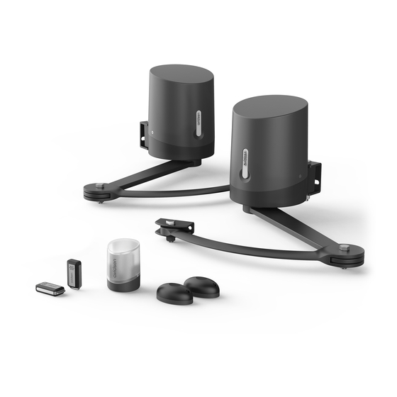
B - PRODUCT DESCRIPTION 1 - KIT CONTENTS Main motor with electronic card M8 washer Secondary motor M8 spring washer Remote control M12 locknut Flashing light and screws M10 nut Rear arm M10 spring washer Front arm M10 washer Post mounting bracket M10 - L120 fastening pin Gate mounting bracket Photocells and screws... -
Page 7: Equipment Required (Not Included)
B - PRODUCT DESCRIPTION 2 - EQUIPMENT REQUIRED (NOT INCLUDED) The tools and screws required for the installation must be in good condition and compliant with applicable safety standards. 1 x 19mm box spanner 1 spirit level 1 measuring 1 pencil and 1 x 13mm box tape 1 drill... -
Page 8: C - Installation
C - INSTALLATION 1. HAZARD ANALYSIS 1.2. Specifications of the gate to motorise 1.1. Regulation This motor drive can automate swing gates up to 2.50m wide and 2.80m high and weighing 250kg. Installation of a motorised gate or a motor drive on These maximum dimensions and weights are for an an existing gate within the framework of “Residential”... -
Page 9: Safety Rules
C - INSTALLATION 1.4. Safety rules The actual opening of a gate may create dangerous situations for people, goods and vehicles in the vicinity that by nature, cannot always be avoided by design. The possible hazards depend on the state of the gate, the manner in which it is used and the installation site. After having checked that the gate to be motorised complies with the requirements given in this chapter and before beginning the installation, a hazard analysis of the installation must be conducted in order to eliminate all dangerous situations or to indicate them if they cannot be eliminated. -
Page 10: Between The Panels And The Fixed Parts Close To Each Other
C - INSTALLATION Hazard Solution swing swing swing 50mm maximum hazardous zone minimum view in profile 2.3. Between the panels and the fixed parts close to each other Depending on the configuration of the site where the motorised gate is installed, there may be confinement areas between the panels in open position and the fixed parts close to them. -
Page 11: Prevention Of Other Hazards
C - INSTALLATION 2.4. Prevention of other hazards The body of a switch with no lock must be located in direct view of the driven part but away from moving parts. Unless it operates with a key, it must be installed at a minimum height of 1.5m and must not be accessible to the public. -
Page 12: Installing The Stops
C - INSTALLATION Tip: Position the motor containing the electronic card on the post where the 230V electrical supply is located. If the 230V electrical supply is already located on the left post, the connections do not need to be reversed. If the electrical supply is located on the right post, it is sufficient to reverse the motor connection polarity in order to reverse the direction of rotation with respect to the assembly described in these instructions (normal mounting with motor and electronic card on the left). -
Page 13: Assembling The Pivoting Arm
C - INSTALLATION Determine the opening angle of each panel based on the data in the following table. The opening angle may be different for each panel but must never be less than 40°. central stop Distance D opening up to (in mm) 90°... -
Page 14: Installing The Motors - For Opening Towards The Inside Of The Property
C - INSTALLATION 3.3 - Installing the motors - for opening towards the inside of the property • Place the mounting brackets against the posts, 14mm above the rigid part of the gate where the ends of the pivoting arms will be fastened. •... - Page 15 C - INSTALLATION • Depending on the maximum opening angle desired for the gate, the post bracket should be placed further from or nearer to the edge of the post (so that the motor does not prevent the gate from opening). For optimum motor operation, the distance X must be as small as possible.
- Page 16 C - INSTALLATION 12mm bit for 12 plugs • Open the cover of the motors • Fasten the motors on the mounting brackets...
- Page 17 C - INSTALLATION Screw 11 Washer 18 Spring washer 17 Nut 16 • Assemble the pivoting arms and motors Washer 12 Washer 14 Screw 10...
- Page 18 C - INSTALLATION • Motor disengagement • Disengage the motors in order to manually manoeuvre the arms. • Close the gate by pressing it firmly against the central stop. • Position the pivoting arms against the gate at a distance of 75cm and mark the location of the holes on the gate.
- Page 19 C - INSTALLATION • Remove the gate bracket from the arm in order to fasten it to the gate. • Use screws and nuts that are suitable for the gate material. • Reassemble the end of the arm and the gate bracket. Important: At this point in the installation, the motors are disengaged.
-
Page 20: Installing The Motors - For Opening Towards The Outside Of The Property
C - INSTALLATION 3.4 - Installing the motors - for opening towards the outside of the property • Place the mounting brackets against the posts, 14mm above the rigid part of the gate where the ends of the pivoting arms will be fastened. Inner side of the property •... - Page 21 C - INSTALLATION 115 mm 12mm bit for 12 plugs • Open the cover of the motors...
- Page 22 C - INSTALLATION • Fasten the motors on the mounting brackets Screw 12 Nut 16 • Assemble the pivoting arms and motors Washer 14 Washer 20 Screw 13...
- Page 23 C - INSTALLATION • Motor disengagement • Disengage the motors in order to manually manoeuvre the arms. • Open the gate up to the side stops. • Turn the pivoting arm to press the gate bracket against the gate as far as possible from the hinges: •...
- Page 24 C - INSTALLATION • Remove the gate bracket from the arm in order to fasten it to the gate. • Use screws and nuts that are suitable for the gate material. • Reassemble the end of the arm and the gate bracket. Important: At this point in the installation, the motors are disengaged.
-
Page 25: Installing The Flashing Light
C - INSTALLATION 4. FLASHING LIGHT INSTALLATION The flashing light must be fastened at the top of the post on which the switchgear is attached and must be visible both inside and outside. Only use the light provided in the kit (24 V - 2 W). The flashing light may be fastened on the wall with or without support. -
Page 26: Installing The Set Of Photocells
C - INSTALLATION 5. ATTACHING THE SET OF PHOTOCELLS 5.1 - Opening inwards 1 set of photocells • Install the reception photocell (RX indicated on the back) on the motor post containing the electronic card. The surface of the posts must be perfectly flat in order to properly align the infrared beam of the photocells. •... -
Page 27: Opening Outwards
C - INSTALLATION 20mm Outer side of the property Outer side of the property Outer side of the property 5.2 - Opening outwards 1 set of photocells • Install the reception photocell (RX indicated on the back) on the motor post containing the electronic card. The surface of the posts must be perfectly flat in order to properly align the infrared beam of the photocells. -
Page 28: 2Nd Set Of Photocells (Optional)
C - INSTALLATION 10 cm min 15 cm max Perfect alignment View from above Inner side of the property 20mm Inner side of the property Inner side of the property Inner side of the property 5.3 - 2 set of photocells (optional) For use when the gate is not visible. -
Page 29: Opening Inwards
C - INSTALLATION 30cm mini 60cm maxi pair 1 90° 90° 10 cm min 15 cm max pair 2 Opening inwards view from above pair 2 10 cm min 15 cm max 90° 90° pair 1 Opening outwards view from above... -
Page 30: Connections
C - INSTALLATION 6. CONNECTIONS • The cable run must comply with applicable standards (NFC 15-100). • Either the cable is 80cm deep with red warning mesh, or the cable is run through a sheath. 230Vac Safety instructions • All electrical connections must be performed with the power switched off (safety switch in OFF position and the battery disconnected). -
Page 31: Motors
C - INSTALLATION 6.2 - Motors For motor wiring without the electronic card, use a 2x1.5mm² cable and an insulating screw joint placed in the motor. Run the cable through the cable clamp and tighten • For inward opening with the motor mounted on the left post OR •... -
Page 32: Photocells
C - INSTALLATION BAT TRANS PROG 6.4 - Photocells BAT TRANS • If there are no photocells, leave the connector between GND and PHO. • With one set of photocells, remove the connector between GND and PHO. photocell RX1 photocell TX1 BAT TRANS NO COM NC •... - Page 33 C - INSTALLATION • HomeGate connected module BAT TRANS 230V AC Install the magnet enabling gate state feedback from the application. • Put the gate in closed position • Install the pre-wired magnet on the panel on the side of the electronic card. Install the passive magnet on the other panel, leaving a gap of no more than 13mm.
-
Page 34: Control Parts (Optional)
C - INSTALLATION BAT TRANS 6.5 - Control parts (optional) Note: These control parts must be normally open dry contacts. push button, intercom output. 6.6 - Backup battery (optional) Note: when the motor is running on the backup battery, the connected module is not working. It is possible to connect a backup battery to perform some manoeuvres in the event of power failure. -
Page 35: Solar Power Kit (Optional)
C - INSTALLATION 6.7 - Solar power kit (optional) Please note that, while the motor drive can be powered by a solar kit, the connected module will not be operational. The 24V solar power kit is plugged into the same connector as the backup battery. The solar power kit (which already has a battery) and a backup battery cannot be connected at the same time. -
Page 36: D - Beginning Operation
D - BEGINNING OPERATION 1. SETTINGS INTERFACE 2. BASIC SETTINGS (MENU 1) Indicators 2.1. Menu Structure After it is switched on, all LEDs will be turned off except the green LED • If the green LED is off, the card is on standby mode. - Page 37 D - BEGINNING OPERATION...
-
Page 38: Photocell Alignment Procedure (Optional)
D - BEGINNING OPERATION 2.2. Photocell alignment procedure (optional) • Closed gate: one press on the gate command opens the gate, which remains open for a certain The electronic card of this motorised gate is on time (adjustable time, see “Time delay”), then standby after 1 minute with no action. -
Page 39: Motor Force
D - BEGINNING OPERATION This time is adjustable from 15 seconds to 90 NOTE: if the force setting is changed, self- seconds and is 15 seconds by default. learning must be repeated. 2.6. Speed 15 s You can adjust the speed by a value of 0 to 4. The 30 s default speed is 4. - Page 40 D - BEGINNING OPERATION SAFETY Make sure not to confuse the self-learning Make sure that there is no one in the gate movement error codes with error codes of events that area during the entire commissioning period and the may occur during normal operation and which entire test period.
-
Page 41: Programming Remote Controls
D - BEGINNING OPERATION 2.8. Programming remote controls In phase 1, motor M1 was not detected It is possible to open both panels (gate) or a single (contact failure, electronic panel (pedestrian) by remote control. card problem?) On a remote control, it is possible to decide which Review motor button will be used as the gate command and which connections. -
Page 42: Advanced Settings
D - BEGINNING OPERATION 2.8.2. Copy programming From a remote control that has already been memorised, you can memorise other remote controls (“copy” function). For each new remote control to be memorised, follow the procedure below • Stand near the motor. •... -
Page 43: (Menus 2 And 3)
D - BEGINNING OPERATION 3.1. Access to advanced settings (MENUS 2 and 3) To access menus 2 and 3, follow the procedure below • Press PROG for 3 seconds. L0 will flash once, L1 will turn on and you will be in menu 1 (basic settings). - Page 44 D - BEGINNING OPERATION 3.2.2. Photocell mode 3.2.3. Type of gate The photocells are active when the panels close To operate the electronic card on a single-panel gate, because they are placed between the posts (pair 1) this setting must be changed. By default, this value is to secure the passage between panels.
-
Page 45: Advanced Settings Menu (Menu 3)
D - BEGINNING OPERATION To adjust this tolerance level, follow the 3.3.1. Panel movement time difference procedure below • Press PROG for 3 seconds. L0 will flash once In general, on closing, one gate panel closes over and L1 will switch on. the other. - Page 46 D - BEGINNING OPERATION 3.3.2 - Pre-flashing time The flashing light is an important safety component. It starts when a command to set the gate in motion is received by the electronic card. The gate is set in motion around one second after a command is received.
-
Page 47: E - Use
Avidsen cannot be held liable for any installation 3. TYPE OF COMMAND or use that does not comply with the instructions and causes damage. It is essential to read the... -
Page 48: Semi-Automatic Closing" Mode
E - USE 4.1. “Semi-automatic closing” mode • 1 second later, panel M2 starts closing. • A few seconds later, panel M1 starts closing. Description of operation from the closed gate • Panel M2 reaches its closing stop. position: • Some time later (2.5 seconds by default, but this time can be adjusted), panel M1 reaches its closing stop. -
Page 49: Obstacle Detection
E - USE • If this is not the case and the beam is obstructed 6. MANUAL MOVEMENT when the gate should start to open, the flashing light will emit double flashes for 30 seconds To manually operate the gate, simply disengage unless a command is activated. -
Page 50: Starting Up The Homegate Connected Module
Once the contactor is connected, follow the instructions below to pair it. Download the Avidsen Home app from the Android Play Store or Apple App Store. Launch the app and log in if you already have an account. -
Page 51: Connecting The Contactor
E - USE Make sure the contactor is connected and its indicator light is flashing. If not, press and hold the reset button for 5s so that the indicator starts flashing. Select your 2.4GHz WiFi network (note: your smartphone must be connected to the WiFi network to which the plug will be connected), enter your network password and press suivant (next). -
Page 52: Use Via The App
(closed or not closed). Your contactor is now operational and will appear in your app. You can now control your Avidsen contactor from your smartphone. You can rename it by clicking on the small pencil to the right of the device name (garage by default). -
Page 53: Using The Product With Google Home
HOME Gate position status (display when in operation) in relation to the magnets NOTE: the name you give your Avidsen Home devices is the one that will be recognised by Alert setting and operating time prior to alert Google Assistant. -
Page 54: If You Have An Android Smartphone With Google Assistant
- In the Amazon Alexa app, press the menu at the top left and select Skills et Jeux (Skills and Games). - Search for Avidsen Home in the list of skills or use Recherche (Search) at the top right. - Select the Avidsen Home Skill and activate for use. -
Page 55: Scenario And Automation
Name your scenario, then click on to set the 11.1 Scenario actions to be executed: The scenario system in the Avidsen Home app allows you to group actions that will be triggered on demand, by clicking on a single button on your smartphone. -
Page 56: Creating An Automation
You can change the background image if you wish is in closed position. Selection of condition type The automation system in the Avidsen Home app Selection of conditions to be met for actions allows you to group devices and actions which will to be executed... - Page 57 E - USE One of the most important settings is the selection of the type de condition (condition type). This allows automation to deal with multiple conditions. Set a temperature weather condition* Set a humidity weather condition* Set a weather condition* •...
- Page 58 E - USE Once all these settings have been confirmed, you can save your automation at the top right Allows you to use a previously defined Scenario (set of actions). Allows you to use a previously defined 11.2.1 Programming “Gate opening”...
- Page 59 E - USE Select the opening time. Slide your finger up or down the time column in the minute column. The time configured will appear between the two parallel lines. You can ask for a repeat of the scenario on different days of the week.
- Page 60 E - USE Rename your scenario at your convenience (in our example: “GATE OPENING”) Once all parameters have been set, click on Save. If you wish to access the details or delete it, click on the “...” icon at the top right of its name.
- Page 61 E - USE...
-
Page 62: F - Maintenance And Upkeep
F - MAINTENANCE AND UPKEEP 1. MAINTENAINCE WORK Maintenance work must be carried out by the installer or a qualified individual to guarantee the installation’s operation and safety. The number of maintenance and upkeep operations must be proportional to the frequency the motorised gate is used. -
Page 63: Operating Indicators
F - MAINTENANCE AND UPKEEP Check the condition of the electronic card (removal of dust, insects, etc.) Check the controls (intercoms, keypad, push button) Check the batteries of the remote controls Check the motor support (deformation, etc.) and the fasteners * do not use grease, as it tends to attract dust or dirt ** please note that adjustments made in summer may need to be changed according to the season (more wind in autumn, frost in winter, etc.) - Page 64 F - MAINTENANCE AND UPKEEP To diagnose any problems, here is the list of codes and their meaning: : LED off : LED on : Flashing LED light There are two types of code: Error (E) or Information (I). N.B. an error requires action from the installer to correct the motor drive problem.
-
Page 65: Manual Control
F - MAINTENANCE AND UPKEEP 2.2 - Manual control • PROG and “+” can be pressed simultaneously, for example to open both panels at the same time. The panels can be manoeuvred without any prior • To exit, press PROG and “–” simultaneously (press programming, for example during motor installation. -
Page 66: Replacing The Power Fuse
F - MAINTENANCE AND UPKEEP 2.5. Replacing the power fuse • Switch the motor drive off. • Use a 250V 5A time-delay fuse... -
Page 67: Compatible Accessories
Solar kit 2. TECHNICAL CHARACTERISTICS The technical characteristics are provided as an indication only and for a temperature of +20°C. The avidsen company reserves the right to modify these characteristics at any time, while under all circumstances guaranteeing these products’ smooth operation and the type of use intended, with a view to improving these products. - Page 68 G - TECHNICAL AND LEGAL INFORMATION Consumption at rated strength Assigned operating duration 10 cycles per hour Maximum number of cycles 100 cycles per day Operating temperature -20°C/ +60°C Protection rating IP44 FLASHING LIGHT LED lighting 8W max, flashing managed Type by the electronic card Power supply...
- Page 69 G - TECHNICAL AND LEGAL INFORMATION - 1 output with normally closed dry contact (COM/NC) Output - 1 output with normally open dry contact (COM/NO) Transmission angle/Reception angle 10° approx. / 10° approx. 15m maximum (range may be reduced due to weather Range disruption) Operating temperature...
-
Page 70: Warranty
If, despite the care we have taken in designing and manufacturing your product, it needs to be returned to our customer service centre. Avidsen undertakes to keep a stock of spare parts for this product throughout the contractual warranty period. -
Page 71: Declaration Of Conformity
EN 301489-1 V2.2.0 EN 301489-3 V2.1.1 Avidsen declares, under its sole responsibility, that the remote control included in the 114202 kit complies with the applicable Union harmonisation legislation. Its conformity has been assessed pursuant to the applicable standards in force: - Directive RED 2014/53/EU EN 300220-1 V3.1.1... - Page 72 Avidsen 19 avenue Marcel Dassault - ZAC des Deux Lions 37200 Tours - France...
Need help?
Do you have a question about the ORANE-CONNECT and is the answer not in the manual?
Questions and answers