
Subscribe to Our Youtube Channel
Related Manuals for EWM RT50 7POL


Summary of Contents for EWM RT50 7POL
- Page 1 Operating instructions Remote control RT50 7POL 099-008793-EW501 Observe additional system documents! 6.3.2023...
- Page 2 +49 2680 181-0. A list of authorised sales partners can be found at www.ewm-group.com/en/specialist-dealers. Liability relating to the operation of this equipment is restricted solely to the function of the equipment. No other f orm of liability, regardless of type, shall be accepted.
-
Page 3: Table Of Contents
6 Maintenance, care and disposal ..................26 General .......................26 Maintenance schedule ...................27 6.2.1 Explanation of icons .................27 Disposing of equipment..................28 7 Technical data ......................29 RT50 7POL ......................29 8 Accessories.........................30 Connection and extension cables ................30 9 Appendix ........................31 Searching for a dealer....................31 099-008793-EW501 6.3.2023... -
Page 4: For Your Safety
For your safety Notes on using these operating instructions For your safety Notes on using these operating instructions DANGER Working or operating procedures which must be closely observed to prevent imminent serious and even fatal injuries. • Saf ety notes include the "DANGER" keyword in the heading with a general warning symbol. •... -
Page 5: Explanation Of Icons
For your safety Explanation of icons Explanation of icons Symbol Description Symbol Description Indicates technical aspects which the Activate and release / Tap / Tip user must observe. Switch off machine Release Switch on machine Press and hold Incorrect / Invalid Switch Correct / Valid Turn... -
Page 6: Safety Instructions
For your safety Saf ety instructions Safety instructions WARNING Risk of accidents due to non-compliance with the safety instructions! Non-compliance with the safety instructions can be fatal! • Caref ully read the safety instructions in this manual! • Observe the accident prevention regulations and any regional regulations! •... - Page 7 For your safety Saf ety instructions WARNING Risk of injury due to improper clothing! During arc welding, radiation, heat and voltage are sources of risk that cannot be avoided. The user has to be equipped with the complete personal protective equipment at all times.
- Page 8 For your safety Saf ety instructions CAUTION Smoke and gases! Smoke and gases may lead to shortness of breath and poisoning! The ultraviolet radia- tion of the arc may also convert solvent vapours (chlorinated hydrocarbon) into poiso- nous phosgene. • Ensure sufficient fresh air! •...
-
Page 9: Transport And Installation
For your safety Transport and installation CAUTION Obligations of the operator! The respective national directives and laws must be complied with when operating the machine! • Implementation of national legislation relating to framework directive 89/391/EEC on the int- roduction of measures to encourage improvements in the safety and health of workers at work and associated individual guidelines. - Page 10 For your safety Transport and installation CAUTION Risk of accidents due to supply lines! During transport, attached supply lines (mains leads, control cables, etc.) can cause risks, e.g. by causing connected machines to tip over and injure persons! • Disconnect all supply lines before transport! Risk of tipping! There is a risk of the machine tipping over and injuring persons or being damaged itself during movement and set up.
-
Page 11: Intended Use
3.3.1 Warranty For more information refer to the "Warranty registration" brochure supplied and our information regarding warranty, maintenance and testing at www.ewm-group.com! 3.3.2 Declaration of Conformity This product corresponds in its design and construction to the EU directives listed in the decla- ration. -
Page 12: Machine Description - Quick Overview
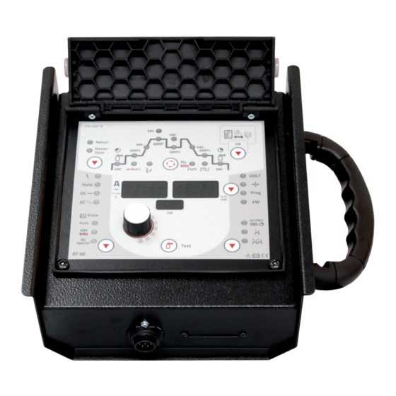
Machine description – quick overview Front view / rear view Machine description – quick overview Front view / rear view Figure 4-1 099-008793-EW501 6.3.2023... - Page 13 Machine description – quick overview Front view / rear view Item Symbol Description Holder for suspending the remote control. Machine control > see 4.2 chapter Protective cap Connection socket, 7-pole (digital) Connection to the digital remote control connection on power source. Machine feet Carrying handle Fixing magnet...
-
Page 14: Machine Control - Operating Elements
Machine description – quick overview Machine control – Operating elements Machine control – Operating elements Basically, all descriptions on the process settings in the standard operating instructions shall apply. This operating manual exclusively describes deviating control functions. Figure 4-2 099-008793-EW501 6.3.2023... - Page 15 Machine description – quick overview Machine control – Operating elements Item Symbol Description Lid > see 4.2.1 chapter Welding data display (3-digit) Displays the welding parameters and the corresponding values Status displays ------ Collective interference signal light Hold ----- Af ter each completed welding task, the last values used in the welding pro- cess f or the welding current and welding voltage are shown on the displays, and the signal light will be on -- Direct current welding...
-
Page 16: Machine Control - Concealed Operating Elements
Machine description – quick overview Machine control – Operating elements 4.2.1 Machine control – Concealed operating elements Figure 4-3 Item Symbol Description Pulse break time/slope time from AMP to AMP% • Pulse break setting range: 0.01 sec to 20.0 sec (0.01 sec increments <... - Page 17 Machine description – quick overview Machine control – Operating elements Item Symbol Description Balance signal light AC balance (TIG)/pulse balance (TIG DC – kHz pulses)/pulse balance (MMA) Signal light, gas post-flow time Press organise welding tasks (JOB) push-button Brief ly pressing the button = display of welding task selected in welding system Holding the button down for long (>...
-
Page 18: Design And Function
Design and function General Design and function General Basically, all descriptions on the process settings in the standard operating instructions shall apply. This operating manual exclusively describes deviating control functions. Scope of delivery The delivery is checked and packaged carefully before dispatch, however it is not possible to exclude the possibility of damage during transit. -
Page 19: Establishing The Connections
Design and function Establishing the connections Establishing the connections CAUTION Risk of accidents due to supply lines! During transport, attached supply lines (mains leads, control cables, etc.) can cause risks, e.g. by causing connected machines to tip over and injure persons! •... -
Page 20: Organising Welding Tasks (Mode "Job Manager")
Design and function Organising welding tasks (Mode "JOB Manager") Organising welding tasks (Mode "JOB Manager") After carrying out any of the actions described, the machine switches back to the default parameters such as current and voltage. To ensure that all the changes are active, the welding machine should only be switched off after 5 seconds have elapsed. -
Page 21: Load Welding Task (Job) From Welding Machine To Remote Control
Design and function Organising welding tasks (Mode "JOB Manager") 5.6.3 Load welding task (JOB) from welding machine to remote control Operating Action Result Display element JOB manager mode selection. Select the required JOB number (e.g. 127) with the rotary transducer. Conf irm selection or wait a short moment for the setting to be automatically applied. -
Page 22: Exit Job Manager Without Changes
Design and function Direct menus (direct access to parameters) 5.6.5 Exit JOB Manager without changes The user is in the JOB manager menu and wants to exit without any changes: Operating Action Result Display element JOB manager mode selection. Select the (END) function with the rotary trans- ducer. -
Page 23: Power-Saving Mode (Standby)
Design and function Power-saving mode (Standby) Display Setting/selection Hot wire process (setting for hot wire current) 5 A to 999 A (5 A ex works, increments of 1 A) Wire/pulse function (wire feeding behaviour when using pulsed TIG welding) Wire feeding can be disabled during pulse pauses (not the case for automated pul- sing or kHz pulsing). -
Page 24: 5.10 Aligning The Cable Resistance
The resistance value of the cables can be set directly or can be aligned by the power source. In the delivery state the cable resistance is set to the optimum values. To optimise the welding properties for other cable lengths, an alignment process (voltage correction) is necessary. RT50 7POL Figure 5-2 099-008793-EW501... -
Page 25: 5.11 Protective Flap, Welding Machine Control
Design and function Protective flap, welding machine control 1 Preparation • Switch off the welding machine. • Unscrew the gas nozzle f rom the welding torch. • Unf asten the tungsten electrode and extract. 2 Configuration • Press the (Tetrix Classic) push-button while simultaneously switching on the welding ma- chine. -
Page 26: Maintenance, Care And Disposal
Maintenance, care and disposal General Maintenance, care and disposal General DANGER Risk of injury due to electrical voltage after switching off! Working on an open machine can lead to fatal injuries! Capacitors are loaded with electrical voltage during operation. Voltage remains present for up to four minutes after the mains plug is removed. -
Page 27: Maintenance Schedule
Maintenance, care and disposal Maintenance schedule Maintenance schedule Maintenance step Only personnel designated as inspectors or repairers due to their trai- ning are allowed to carry out the relevant work step! Non-applicable in- spection points are omitted. • Checking all supply lines and their connections (pipes, hoses, hose packages) for damage or leaks. -
Page 28: Disposing Of Equipment
Inf ormation on returning used equipment or collections can be obtained from the respective municipal administration office. Devices can also be returned to EWM sales partners across Europe. Further inf ormation on the topic of the disposal of electrical and electronic equipment can be found on our website at: https://www.ewm-group.com/de/nachhaltigkeit.html. -
Page 29: Technical Data
Technical data RT50 7POL Technical data Performance specifications and guarantee only in connection with original spare and replacement parts! RT50 7POL Connection 7-pole Ambient temperature -25 °C to +40 °C Test mark Standards used See declaration of conformity (appliance documents) Dimensions (l x b x h) 115 x 235 x 300 mm / 4.5 x 9.3 x 11.8 inch... -
Page 30: Accessories
Accessories Connection and extension cables Accessories Connection and extension cables Type Designation Item no. FRV 7POL 0.5 m Extension/connecting cable 092-000201-00004 FRV 7POL 1 m Extension/connecting cable 092-000201-00002 FRV 7POL 5 m Extension/connecting cable 092-000201-00003 FRV 7POL 10 m Extension/connecting cable 092-000201-00000 FRV 7POL 20 m Extension/connecting cable... -
Page 31: Appendix
Appendix Searching for a dealer Appendix Searching for a dealer Sales & service partners www.ewm-group.com/en/specialist-dealers "More than 400 EWM sales partners worldwide" 099-008793-EW501 6.3.2023...
Need help?
Do you have a question about the RT50 7POL and is the answer not in the manual?
Questions and answers