Advertisement
Quick Links
Z_ISE40A-TF2Z052EN
ORIGINAL INSTRUCTIONS
Instruction Manual
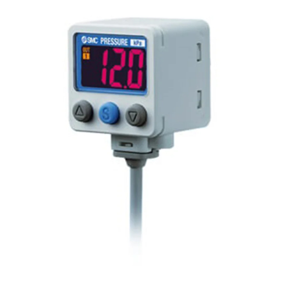
Digital Pressure Switch
Series ZSE40A(F) / ISE40A
The intended use of this digital pressure switch is to measure, monitor
and display pressure and to provide an output signal.
1 Safety Instructions
These safety instructions are intended to prevent hazardous situations
and/or equipment damage. These instructions indicate the level of
potential hazard with the labels of "Caution," "Warning" or "Danger."
They are all important notes for safety and must be followed in addition
*1)
to International Standards (ISO/IEC)
, and other safety regulations.
*1)
ISO 4414: Pneumatic fluid power - General rules relating to systems.
ISO 4413: Hydraulic fluid power - General rules relating to systems.
IEC 60204-1: Safety of machinery - Electrical equipment of machines.
(Part 1: General requirements)
ISO 10218-1: Robots and robotic devices - Safety requirements for
industrial robots - Part 1: Robots.
• Refer to product catalogue, Operation Manual and Handling
Precautions for SMC Products for additional information.
• Keep this manual in a safe place for future reference.
Caution indicates a hazard with a low level of risk which, if
Caution
not avoided, could result in minor or moderate injury.
Warning indicates a hazard with a medium level of risk
Warning
which, if not avoided, could result in death or serious injury.
Danger indicates a hazard with a high level of risk which, if
Danger
not avoided, will result in death or serious injury.
Warning
• Always ensure compliance with relevant safety laws and
standards.
• All work must be carried out in a safe manner by a qualified person in
compliance with applicable national regulations.
• This product is class A equipment intended for use in an industrial
environment. There may be potential difficulties in ensuring
electromagnetic compatibility in other environments due to conducted
or radiated disturbances.
Otherwise electric shock, malfunction or product damage can result.
• Refer to the operation manual on the SMC website (URL:
https://www.smcworld.com) for more safety instructions.
• Special products (-X) might have specifications different from those
shown in the specifications section. Contact SMC for specific
drawings.
2 Specifications
2.1 General specifications
ZSE40A
ZSE40AF
ISE40A
Model No.
(vacuum)
(compound)
(positive)
0 to -101.3
-100.0 to
-0.100 to
Rated pressure range
kPa
100.0 kPa
1.000 MPa
10.0 to -
-105.0 to
-0.105 to
Set pressure range
105.0 kPa
105.0 kPa
1.050 MPa
Withstand pressure
500 kPa
500 kPa
1.5 MPa
Minimum display unit
0.1 kPa
0.1 kPa
0.001 MPa
Applicable fluid
Air, inert gases and incombustible gases
12 to 24 VDC ±10%, ripple (p-p) 10% or less
Power supply voltage
(protected against reverse connection)
Current consumption
45 mA or less
Switch output
NPN or PNP open collector 2 outputs
Max. load current
80 mA
Max. applied
28 V (NPN output)
voltage
Residual voltage
1 V or less (at 80 mA load current)
2.5 ms or less
Response time
(with anti-chatter function: 20, 100, 500, 1000
or 2000 ms)
Protection
Short circuit protection
Repeatability
±0.2% F.S. ±1 digit
Hysteresis
0 to variable
Output voltage
0.6 to 5 V
1 to 5 V ±2.5% F.S.
(rated pressure)
±2.5% F.S.
Linearity
±1% F.S.
Output
Approx. 1 kΩ
impedance
Output current
2.4 to 20 mA
4 to 20 mA ±2.5% F.S.
(rated pressure)
±2.5% F.S.
Linearity
±1%F.S.
Max. load impedance: 300 Ω (at 12 VDC)
Load
600 Ω (at 24 VDC)
impedance
Min. load impedance: 50 Ω
Non-voltage input (reed or solid state),
Auto-shift input
Low level 0.4 V or less, input time 5 ms min.
3½ digits, 7-segment, dual-colour display
Display
(red/green)
±2% F.S. ±1 digit (at 25 ±3 °C)
Display accuracy
LED is ON when output is ON
Indicator LED
OUT: Orange
Enclosure
IP65
Operation: -5 to 50 °C, Storage: -10 to 60 °C
Operating
temperature range
(no condensation or freezing)
Operating humidity
Operation, Storage: 35 to 85% RH (no
range
condensation)
1000 VAC, 1 minute between terminals and
Withstand voltage
housing
50 MΩ or more at 500 VDC between
Insulation resistance
terminals and housing
Surrounding air temperature rating:
UL Temperature rating
o
Maximum 50
C
Temperature
±2% F.S. (at 25 °C reference)
characteristics
Oil resistant vinyl cabtyre cable
φ3.5, 2 m
5 cores
Lead wire
Conductor:
0.15 mm
2
(AWG26)
O.D. of insulator:
0.95 mm
2.2 Piping / Weight specifications
Model No.
01
N01
W1
WF1
M5
C4
R1/8
NPT1/8
One-
M5
Port size
(M5
(M5
Rc1/8
G1/8
touch
female
fitting φ4
female)
female)
Sensor
Silicone
ZDC2, POM,
C3602
SUS304, C3604
Piping
(electroless
ZDC2
(electroless nickel
port
nickel plating)
O-ring: HNBR
plating)
O-ring: HNBR
O-ring: HNBR, NBR
Weight
78 g
79 g
97 g
97 g
104 g
101 g
3 Name and function of parts
Indicator LED (Orange LED): Displays the switch output condition.
LCD display:
Displays the current status of pressure, setting mode and
error code.
Four display modes can be selected: display always in
red or green, or display changing from green to red, or
red to green, according to the output status.
button (UP):
Selects the mode or increases the ON/OFF set
value. Press this button to change to the peak
display mode.
button (DOWN): Selects the mode or decreases the ON/OFF set
value. Press this button to change to the bottom
display mode.
button (SET):
Press this button to change to another mode and to
set a value.
4 Installation
4.1 Installation
Warning
• Do not install the product unless the safety instructions have been read
and understood.
• When the product is to be mounted in a place where water and dust
splashes occur, insert a tube (O.D φ4 mm, I.D φ2.5 mm) into the
atmospheric vent port of the product.
4.1.1 Mounting with bracket
• Mount the bracket to the product with the mounting screws M3 x 5L (2
pcs.) or M4 x 5L (2 pcs.) supplied, then set the product in the required
position.
∗: The required tightening torque is 0.5 to 0.7 N•m for the M3 set screws
and 1.4 to 1.6 N•m for the M4 set screws.
Bracket A or D (Part No.: ZS-24-A / ZS-24-D)
[01 / N01 type]
[W1 / WF1 type]
C6
One-
touch
fitting φ6
For products with M8 (3 pin) connector, be sure to reserve a space for
101 g
the lead wire and connector.
4 Installation (continued)
Bracket B (Part No.: ZS-24-B)
4.1.2 Mounting with panel mount adapter
• Products with M8 (3 pin) connector cannot be panel mounted.
• Panel mount adapter (Part No.: ZS-35-C / ZS-35-D)
Panel mount adapter + Front protective cover (Part No.: ZS-35-F / -G).
∗: The panel mount adapter can be rotated through 90 degrees for mounting.
4.2 Environment
Warning
• Do not use in an environment where corrosive gases, chemicals, salt
water or steam are present.
• Do not use in an explosive atmosphere.
• Do not expose to direct sunlight. Use a suitable protective cover.
• Do not install in a location subject to vibration or impact. Check the
product specifications.
• Do not mount in a location exposed to radiant heat.
• Do not use the product in a place where electrical static charge will be
a problem. It can cause the error and damage to the system.
4.3 Piping
Caution
• Before piping make sure to clean up chips, cutting oil, dust etc.
• When installing piping or fittings, ensure sealant material does not
enter inside the port. When using seal tape, leave 1 thread exposed
on the end of the pipe/fitting.
• Tighten fittings to the specified tightening torque.
4.3.1 Connection using screw type fitting
• Connect suitable piping to the port.
• Hold the hexagon part of the piping port and fix. The required tightening
torque is 7 to 9 N•m.
• When using an M5 female fitting confirm the fitting specification.
Page 1 of 3
Advertisement

Related Manuals for SMC Networks ZSE40A Series


Summary of Contents for SMC Networks ZSE40A Series
- Page 1 Z_ISE40A-TF2Z052EN 2 Specifications 3 Name and function of parts 4 Installation (continued) ORIGINAL INSTRUCTIONS 2.1 General specifications Bracket B (Part No.: ZS-24-B) ZSE40A ZSE40AF ISE40A Model No. (vacuum) (compound) (positive) Instruction Manual 0 to -101.3 -100.0 to -0.100 to Rated pressure range Digital Pressure Switch 100.0 kPa 1.000 MPa...
- Page 2 Z_ISE40A-TF2Z052EN 4 Installation (continued) 6 Pressure Setting 6 Pressure Setting (continued) 7 Function Setting (continued) • [F 1] Setting of OUT1 4.3.2 Connection using One-touch fitting 6.1 Measurement mode Press the button once to decrease by one digit, and press it continuously to keep decreasing the set value.
- Page 3 Z_ISE40A-TF2Z052EN 11 Error Indication 12 Maintenance 12.1 General Maintenance Error Troubleshooting Caution Error Name Error Type Display Method • Not following proper maintenance procedures could cause the product Turn the power off The switch to malfunction and lead to equipment damage. Over and remove the output load...
Need help?
Do you have a question about the ZSE40A Series and is the answer not in the manual?
Questions and answers