Table of Contents

Subscribe to Our Youtube Channel
Related Manuals for Relay2 RA200


Summary of Contents for Relay2 RA200
- Page 1 H A R D W A R E I N S T A L L A T I O N G U I D E RA200 SERVICE-READY ACCESS POINT Doc No.: PRDT-0046 | Version 2.0 | Date 2023-08-23 ©2023 by Relay2, Inc. All Rights Reserved | www.relay2.com | (408) 380-0031 | sales@relay2.com...
- Page 2 This device follows FCC Part 15. Two general conditions of operation: 1. No harmful interference is caused by this device. 2. This device can accept interference that may be caused by unexpected operation. ©2023 by Relay2, Inc. All Rights Reserved | www.relay2.com | (408) 380-0031 | sales@relay2.com...
-
Page 3: Warranty
Relay2, Inc. ©2023 by Relay2, Inc. All Rights Reserved | www.relay2.com | (408) 380-0031 | sales@relay2.com... -
Page 4: Accessories List
ACCESSORIES LIST PICTURE COMPONENT NAME QTY. Universal Mount Kit Universal Mount Kit Screw Set for Mounting Kit Power Adapter Power Adapter (Optional) Power Cord ©2023 by Relay2, Inc. All Rights Reserved | www.relay2.com | (408) 380-0031 | sales@relay2.com... -
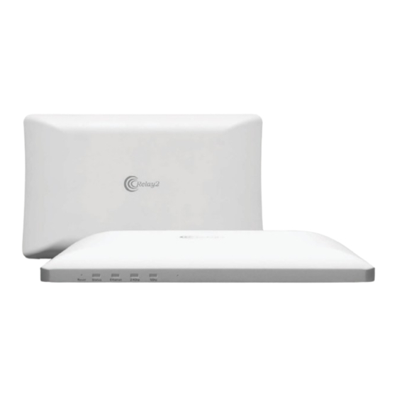
Page 5: Display And Leds
DISPLAY AND LEDS WLAN Access Point (Front) Reset Button LED Function Altitude Sensor ©2023 by Relay2, Inc. All Rights Reserved | www.relay2.com | (408) 380-0031 | sales@relay2.com... - Page 6 WLAN Access Point Interfaces (Back) DC in/48-VDC RJ45 Port RJ9 Port to RS (For diagnostics) USB Port (For additional accessories) 3G/4G Dongle Compartment Air Circulation Holes ©2023 by Relay2, Inc. All Rights Reserved | www.relay2.com | (408) 380-0031 | sales@relay2.com...
- Page 7 SIGNAL COVERAGE AREA Wall Install Reference A: Strong signal coverage area B: Weak signal coverage area Table ©2023 by Relay2, Inc. All Rights Reserved | www.relay2.com | (408) 380-0031 | sales@relay2.com...
-
Page 8: Ceiling Installation
Tighten the screws to lock the sliders in place. Check to ensure the mount is secure. Tighten the Screws ©2023 by Relay2, Inc. All Rights Reserved | www.relay2.com | (408) 380-0031 | sales@relay2.com... - Page 9 Plate, then gently pull the entire AP toward the direction indicated by the arrow until the AP is securely locked into place. Complete Assembly (Ceiling Installation) ©2023 by Relay2, Inc. All Rights Reserved | www.relay2.com | (408) 380-0031 | sales@relay2.com...
-
Page 10: Wall Installation
WALL INSTALLATION The universal mount can also be used to install the RA200 on walls. Drywall, plasterboard, and other similar indoor wall materials are suitable to secure the access point. AP Bottom M5 Self-Tapping Screws (4x) Plastic Screw Anchors (4x) - Page 11 Mark the positions for the holes. Place the mount against the wall and fasten it with the M5 Screws as shown below. Plastic Anchor (4x) M5 Screw (4x) ©2023 by Relay2, Inc. All Rights Reserved | www.relay2.com | (408) 380-0031 | sales@relay2.com...
- Page 12 4. Slide the four mounting pegs on the back of the AP into the holes of the mounting bracket, then slightly pull in the direction of arrow B. The AP will not be positioned on the bracket. V-shaped positioning latch ©2023 by Relay2, Inc. All Rights Reserved | www.relay2.com | (408) 380-0031 | sales@relay2.com...
- Page 13 Complete Assembly (Ceiling Installation) ©2023 by Relay2, Inc. All Rights Reserved | www.relay2.com | (408) 380-0031 | sales@relay2.com...
-
Page 14: Hardware Specifications
LED Indicators 1x power status Indicator 1x Ethernet connectivity indicator 1x 2.4 GHz indicator 1x 5 GHz indicator Regulatory FCC (US), TA (China) Certifications Wi-Fi Certified ©2023 by Relay2, Inc. All Rights Reserved | www.relay2.com | (408) 380-0031 | sales@relay2.com... - Page 15 This equipment should be installed and operated with a minimum distance of 20 cm between the radiator and your body. Operations in the 5.15–5.35 GHz band are restricted to indoor usage only. ©2023 by Relay2, Inc. All Rights Reserved | www.relay2.com | (408) 380-0031 | sales@relay2.com...
Need help?
Do you have a question about the RA200 and is the answer not in the manual?
Questions and answers