
Subscribe to Our Youtube Channel
Related Manuals for Relay2 RA200


Summary of Contents for Relay2 RA200
- Page 1 Hardware Installation Guide Relay2 RA200 Service-Ready Access Point Doc No.: PRDT- Version:1. Date: 2017-09-14 Copyright © Relay2, Inc. 2017. All rights reserved.
- Page 2 FCC authorization. Product Overview: The RA200 family is a cloud-managed Service-Ready Access Point (SR-AP) o ering edge computing and storage capabilities with high-performance wireless access point integrated. It enables businesses to deliver superior venue experiences, enhance business operations, and create competitive advantages.
-
Page 3: Opening The Package
Please provide the device model, MAC address and serial number shown on the tag of the rear panel. The warranty does not cover product that has been opened without authorization from Relay2 Inc. Reasonable repair and shipping cost will be charged for product fault or damage caused by using non-Relay2 accessories or improper operation. - Page 4 Relay2 RA200 Service-Ready Access Point Hardware Installation Guide Accessories List Picture Component Name Qty. Screw Power Adapter Power Cord PRDT-00 © Relay2, Inc. 2017. All rights reserved.
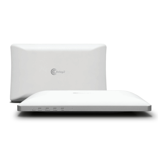
- Page 5 Relay2 RA200 Service-Ready Access Point Hardware Installation Guide Display and LEDs WLAN Access Point (Front) Reset Button Altitude Sensor LED Function PRDT-00 © Relay2, Inc. 2017. All rights reserved.
- Page 6 Relay2 RA200 Service-Ready Access Point Hardware Installation Guide I/O Interface WLAN Access Point Interfaces (Back) RJ45 Port RJ9 Port (RJ9 to RS232) (for diagnostics) USB Port (for additional accessories) 3G/4G Dongle Compartment Air Circulation Holes PRDT-00 © Relay2, Inc. 2017. All rights reserved.
-
Page 7: Installation Reference
Relay2 RA200 Service-Ready Access Point Hardware Installation Guide Signal Coverage Area 30° Installation reference: A: Strong signal coverage area. B: Weak signal coverage area. 30° 30° 30° Table PRDT-00 © Relay2, Inc. 2017. All rights reserved. - Page 8 Relay2 RA200 Service-Ready Access Point Hardware Installation Guide Universal Mount Slide Handle PRDT-00 © Relay2, Inc. 2017. All rights reserved.
- Page 9 Relay2 RA200 Service-Ready Access Point Hardware Installation Guide V-shaped positioning Latch Mounting pegs (4) Slide the AP’s four mounting 3.0: pegs into receiving slots on the Universal Mount Plate, then gently pull the entire AP towards the direction indicated by the arrow until the AP is securely locked into place.
-
Page 10: Wall Installation
Relay2 RA200 Service-Ready Access Point Hardware Installation Guide Wall Installation plasterboard, and other similar indoor wall materials are suitable to secure the access point to. Mounting Plate PRDT-00 © Relay2, Inc. 2017. All rights reserved. - Page 11 Relay2 RA200 Service-Ready Access Point Hardware Installation Guide PRDT-00 © Relay2, Inc. 2017. All rights reserved.
- Page 12 Relay2 RA200 Service-Ready Access Point Hardware Installation Guide V shaped positioning latch PRDT-00 © Relay2, Inc. 2017. All rights reserved.
- Page 13 Relay2 RA200 Service-Ready Access Point Hardware Installation Guide (Wall Installation) PRDT-00 © Relay2, Inc. 2017. All rights reserved.
- Page 14 Relay2 RA200 Service-Ready Access Point Hardware Installation Guide PRDT-00 © Relay2, Inc. 2017. All rights reserved.
-
Page 15: Fcc Disclaimer
Relay2 RA200 Service-Ready Access Point Hardware Installation Guide FCC Disclaimer § 15.19 Labelling requirements. This device complies with part 15 of the FCC Rules. Operation is subject to the following two conditions: (1) This device may not cause harmful interference, and (2) this device must accept any interference received, including interference that may cause undesired operation.
Need help?
Do you have a question about the RA200 and is the answer not in the manual?
Questions and answers