
Related Manuals for Honeywell SILENT KNIGHT SK-PS6


Summary of Contents for Honeywell SILENT KNIGHT SK-PS6
- Page 1 SK-PS6 & SK-PS10 Power Supplies Instruction Manual Document LS10227-002SK-E Rev: C 2/2/2022 ECN: 00006488...
- Page 2 Fire Alarm & Emergency Communication System Limitations While a life safety system may lower insurance rates, it is not a substitute for life and property insurance! An automatic fire alarm system—typically made up of smoke IMPORTANT! Smoke detectors must be installed in the same room detectors, heat detectors, manual pull stations, audible warning as the control panel and in rooms used by the system for the devices, and a fire alarm control panel (FACP) with remote...
- Page 3 Flexput®, Honeywell®, JumpStart®, Silent Knight®, and SWIFT® are registered trademarks of Honeywell International Inc. Microsoft® and Windows® are registered trademarks of the Microsoft Corporation. Chrome™ and Google™ are trademarks of Google Inc. Firefox® is a registered trademark of The Mozilla Foundation.
- Page 4 Your suggestion for how to correct/improve documentation Send email messages to: FireSystems.TechPubs@honeywell.com Please note this email address is for documentation feedback only. If you have any technical issues, please contact Technical Services. This symbol (shown left) on the product(s) and / or accompanying documents means that used electrical and electronic products should not be mixed with general household waste.
-
Page 5: Table Of Contents
Table of Contents Section 1: System Overview............................. 8 1.1: General..........................................8 1.2: Features..........................................8 1.3: Specifications........................................8 1.4: Open/Short/Ground Fault Trip Values in Standby.............................9 1.5: Switch SW1 - Ground Fault Detection................................10 1.6: Applications ........................................12 1.7: Start-up Procedure ......................................12 Section 2: Installation ..............................13 2.1: Backbox Mounting ......................................13 2.2: NAC Circuit Wiring......................................14 2.2.1: Class B ........................................14... - Page 6 Table of Contents 7.2: Battery Checks and Maintenance ..................................41 Appendix A: Wire Requirements............................ 42 Appendix B: Application Examples ..........................43 B.1: Controlling NACs For Selective Silence Operation Using a Control Module ....................43 B.2: Controlling NACs For Sync Follower Operation Using a Control Module (Default Mode Configuration Only).........44 B.3: Controlling NACs, Aux Power, or Door Holders Using a Control Module ....................45 B.4: Controlling NACs, Aux Power, and Door Holders with NAC Sync ......................46 B.5: Controlling all Three Inputs with One Control Module..........................47...
- Page 7 It is imperative that the installer understand the requirements of the Authority Having Jurisdiction (AHJ) and be familiar with the standards set forth by the following regulatory agencies: • Underwriters Laboratories Standards • NFPA 72 National Fire Alarm Code Before proceeding, the installer should be familiar with the following documents. NFPA Standards NFPA 72 National Fire Alarm Code NFPA 70 National Electrical Code...
-
Page 8: Section 1: System Overview
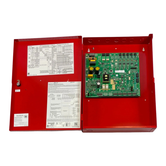
Section 1: System Overview The SK-PS6 is a 6 amp and the SK-PS10 is a 10 amp remote power supply with battery charger. Both models provide ADA compatible strobe synchronization and a filtered 24 VDC output that can be configured to drive five (6 amp model) or seven (10 amp model) Class B NACs (Notification Appliance Circuits). -
Page 9: Open/Short/Ground Fault Trip Values In Standby
Open/Short/Ground Fault Trip Values in Standby System Overview • Wire size: #12-14 AWG wire with 600V insulation Command Input Circuits - TB5, TB6, TB7 • Trigger Input Voltage: 9 - 32 VDC • Input Current Draw in Alarm Polarity: 9 - 32 volts, 14.0 mA maximum per input Output Circuits - TB8-TB14 •... -
Page 10: Switch Sw1 - Ground Fault Detection
System Overview Switch SW1 - Ground Fault Detection Value of the resistance in between any circuit terminal to Earth, which will cause the Ground Fault detection, depends on the ELR chosen for inputs and output circuits. This resistance will vary from 9.9K down to 0 Ohm. Table 1.2 lists the open/short trip values and restoral values in standby for the NAC circuits on the FACP. - Page 11 Switch SW1 - Ground Fault Detection System Overview Power-limited (Class 2), Supervised, Special Note: The SK-PS6 uses the same PCB Application or Regulated Outputs layout, however some terminals will be NAC/Out 7 - depopulated, leaving the SK-PS6 with five NAC/Out 7 + output circuits and two inputs circuits.
-
Page 12: Applications
System Overview Applications 1.6 Applications The SK-PS may be used in a number of different applications. It may be used as a remotely-mounted power supply and battery charger where it can provide up to seven coded or non-coded, synchronized or non-synchronized NACs (Notification Appliance Circuits). Alterna- tively, any output can be used as a door holder circuit which will provide a steady 24 VDC output until an alarm condition or AC fail condi- tion causes it to drop to 0 VDC following a selectable delay. -
Page 13: Section 2: Installation
Section 2: Installation Carefully unpack the system and check for shipping damage. Select a location for the cabinet that is in a clean, dry, vibration-free area where extreme temperatures are not encountered. The area should be readily accessible with sufficient room to easily install and maintain the power supply. -
Page 14: Nac Circuit Wiring
Installation NAC Circuit Wiring 2.2 NAC Circuit Wiring 2.2.1 Class B The standard configuration for NACs is Class B as shown below. Use Listed ELRs supplied by the FACP or compatible equipment manufac- turer. 2k-27kΩ ELR Alarm Polarity Shown Horn Strobe Horn Strobe Horn Strobe SK-PS Circuit Board... -
Page 15: Addressable Module Mounting
Addressable Module Mounting Installation 2.3 Addressable Module Mounting The SK-PS has been designed to allow the mounting of an addressable control, relay, or monitor module on the main circuit board inside the power supply cabinet. This allows power to be fed from an SK-PS output circuit directly to the module, if needed, without running the power wires outside the cabinet. -
Page 16: Nec Power-Limited (Class 2) Wiring Requirements
Installation NEC Power-limited (Class 2) Wiring Requirements 2.4 NEC Power-limited (Class 2) Wiring Requirements Power-limited (Class 2) and non-power-limited circuit wiring must remain separated in the cabinet. All power-limited (Class 2) circuit wir- ing must remain at least 0.25” away from any non-power-limited circuit wiring and all power-limited (Class 2) circuit wiring and non-power- limited circuit wiring must enter and exit the cabinet through different conduits. -
Page 17: Facp With Sk-Ps Power Supply In Slave Configuration
FACP with SK-PS Power Supply in Slave Configuration Installation 2.5 FACP with SK-PS Power Supply in Slave Configuration In this application, the power supply is configured as a Slave unit and connected to a master FACP programmed for synchronized output. . ELR for FACP NAC programmed for sync... -
Page 18: Connecting To An External Charger
Installation Connecting to an External Charger Use only devices from the same manufacturer in each zone or field of view. In this example, the output is mapped to Input#1 in Master Configuration, but it can programmed to another input using the DIP switches. -
Page 19: Connecting Multiple Power Supplies
Connecting Multiple Power Supplies Installation 2.8 Connecting Multiple Power Supplies 2.8.1 Cascading Multiple Units Up to four SK-PS power supplies can be cascaded together to provide additional NAC extenders for a system. Maintain separation of power- limited and non-power-limited wiring as shown in Figure 2.6 on page 16. Figures 2.11 and 2.12 show the controlling signal connected to Input 1 of SK-PS1. -
Page 20: 2: Daisy-Chaining Multiple Units
Installation Ground Fault Detection 2.8.2 Daisy-chaining Multiple Units The number of power supplies which can be daisy-chained is limited by the line resistance and current draw limitations of the upstream mod- ule or NAC output circuit. Refer to the module, power supply, or fire alarm control panel manual to confirm these circuit specifications. Maintain separation of power-limited and non-power-limited wiring as shown in Figure 2.6. - Page 21 Ground Fault Detection Installation battery terminals, including FACP battery terminal. Ground faults must then be detected by the first SK-PS in the chain. Disable ground fault detection on other SK-PS units by sliding SW1 to the left. Ensure ground fault detection is enabled on SK-PS1, the first power supply from the FACP, by sliding SW1 to the right.
- Page 22 Installation Ground Fault Detection Conventional FACP: The FACP must be programmed to turn on the common trouble LED, trouble tone, and a separate yellow annunciator point when the input connected to the SK-PS ground fault relay is initiated. Use one input per SK-PS power supply. Input 1 Input 2 NO NC C...
-
Page 23: Section 3: Programming Options
Section 3: Programming Options NOTICE TO USERS, INSTALLERS, AUTHORITIES HAVING JURISDICTION AND OTHER INVOLVED PARTIES This product incorporates field-programmable software. In order for the product to comply with the requirements in the Standard for Control Units and Accessories for Fire Alarm Systems, UL 864, certain programming features or options must be limited to specific values or not used at all as indicated below: Permitted in Settings permitted in Program feature or option... -
Page 24: S1 Global Options Dip Switch
Programming Options S1 Global Options DIP Switch 3.1 S1 Global Options DIP Switch The following table lists the global control options for the SK-PS programmable features and the switch settings required to select a particu- lar feature. A detailed description of each feature is presented in the following pages. Refer to Table 3.1 for UL-compliant settings. S1 DIP Switch Function 1, 2... -
Page 25: Command Input #1
S1 Global Options DIP Switch Programming Options Command Input #1 Power supply Output circuits can be configured to “follow” a sync pattern that is input to Command Input #1 (TB5), either immediately (Input#1 Normal Configuration), or only after a trigger signal (Input #1 Sync Configuration) is applied at Command Input #2 (TB6) or Com- mand Input #3 (TB7), if applicable. -
Page 26: Ac Fail Indication Delay
Programming Options S1 Global Options DIP Switch AC Fail Indication Delay The AC Fail Indication Delay feature provides the option to delay generation of a trouble signal upon the loss of AC power. Refer to Table 3.1 for UL-compliant settings. ... -
Page 27: Output Circuit Control Dip Switch Settings
Output Circuit Control DIP Switch Settings Programming Options Display Trouble History Mode To see past troubles on the system, place position 9 to OFF and position 10 to ON. Refer to Section 4 for descriptions of troubles. Trouble history will be erased upon exiting the Display Trouble History operating mode. The behavior of the Display Trouble History Mode with regard to the Sync Input Configuration and Trouble reporting will depend on which was the last active (minimum 5 minutes) operating mode, Default or Retrofit, before entering Display Trouble History Mode. -
Page 28: 1: Output Circuit Programmable Features Description
Programming Options Output Circuit Control DIP Switch Settings 3.2.1 Output Circuit Programmable Features Description Command Inputs/NAC Circuit Activation The SK-PS allows for individual NAC circuit programming. Each NAC can be configured to activate based on the settings selected for up to 3 command inputs. -
Page 29: Door Holder
Output Circuit Control DIP Switch Settings Programming Options Door Holder Each output circuit can be configured as a door holder circuit. Setting DIP switch positions according to Table 3.13 will configure the selected output circuit as a door holder circuit which will provide a steady 24 VDC to door holders until a mapped input activates an alarm or when an AC fail condition removes the power following a programmable delay. -
Page 30: Class A Wiring
Programming Options Output Circuit Control DIP Switch Settings Class A Wiring NAC circuits (all outputs) and aux power circuits (outputs 1 and 2) can be converted to Class A wiring using the ZNAC-PS option card. Set- ting DIP switch position 7=ON when a selected output circuit is configured for Class A wiring. The default setting is OFF for Class B wir- ing. -
Page 31: Section 4: Led Indicators
Section 4: LED Indicators The SK-PS power supply has 3 system LED indicators for Power, Batt/Chgr Fault, and Ground Fault. In addition, each available output cir- cuit also has 2 status LEDs. Refer to Figure 1.1 on page 11 for LED locations. A description of each SK-PS LED indication is given below. Ground Fault LED (yellow) No Fault LED is OFF... - Page 32 LED Indicators Output Circuit Status LEDs (red) Output inactive LED is OFF Output active LED is ON constant Output Circuit Trouble LEDs (yellow) No Fault LED is OFF Fault Condition: Repeating LED blink pattern (non-diagnostic phase and diagnostic phase) Wire Supervision Class A or B Open circuit Retrofit pause...
- Page 33 Notes SK-PS Series Instruction Manual — P/N LS10227-002SK-E:C 2/2/2022...
-
Page 34: Section 5: Trouble Supervision
Section 5: Trouble Supervision The FACP will detect SK-PS power supply faults. Any of the following conditions will cause the trouble contact to open, provided the FACP Notification Appliance Circuit is not in alarm. 5.1 Trouble Supervision Using Input Circuits The FACP (Fire Alarm Control Panel) supervises the connection between itself and the SK-PS via the control panel’s NAC End-of-Line Resistor (ELR). -
Page 35: General Trouble Relay
General Trouble Relay Trouble Supervision 5.2 General Trouble Relay The SK-PS power supply has a fail-safe Form-C trouble relay located at TB1. The contacts can be monitored by an FACP input circuit or an addressable monitor module as illustrated in Figure 5.1. Note that any faults reported by Command Inputs are not repeated by the trouble relay in Default Mode, offering limited trouble reporting. -
Page 36: Ac Trouble Relay
Trouble Supervision AC Trouble Relay 5.3 AC Trouble Relay The SK-PS power supply has a fail-safe Form-C trouble relay located at TB2. The contacts can be monitored by an FACP input circuit or an addressable monitor module similar to the drawing illustrated in Figure 5.1. The AC Trouble Relay responds to an AC fail condition on the SK-PS immediately, or after a programmed delay time, depending on the setting of S1 switches 7 and 8. - Page 37 Notes SK-PS Series Instruction Manual — P/N LS10227-002SK-E:C 2/2/2022...
-
Page 38: Section 6: Power Supply Requirements
Section 6: Power Supply Requirements 6.1 Overview This section contains instructions and tables for calculating power supply currents in alarm and standby conditions. This is a four-step pro- cess, consisting of the following: Calculating the total amount of AC branch circuit current required to operate the system Calculating the power supply load current for secondary non-fire and fire alarm conditions Calculating the size of batteries required to support the system if an AC power loss occurs Selecting the proper batteries for your system... -
Page 39: 2: How To Calculate System Current Draw
Selecting and Locating Batteries Power Supply Requirements 6.3.2 How to Calculate System Current Draw Use Table 6.3 to calculate current draws as follows and refer to the battery calculation tool on www.silentknight.com or www.farenhyt.com. Enter the quantity of devices in both columns. Enter the current draw where required. -
Page 40: 2: Maximum Battery Standby Load
Power Supply Requirements Selecting and Locating Batteries 6.4.2 Maximum Battery Standby Load Tables 6.4 and 6.5 show the standby load calculations for the power supply based on 24 hours of standby. The standby load calculations in the Table 6.3 must be less than the number shown in Tables 6.4 and 6.5 for the selected battery size, standby hour and alarm time. The num- bers below have a built in 20% derating factor for the battery ampere capacity. -
Page 41: Section 7: Testing And Maintenance
Section 7: Testing and Maintenance 7.1 Periodic Testing and Service Periodic testing and servicing of equipment is essential to ensure proper and reliable operation. Test and service the power supply according to the schedules and procedures outlined in the following documents: •... -
Page 42: Appendix A: Wire Requirements
Appendix A: Wire Requirements Connecting external system accessories to the main circuits must be carefully considered to ensure proper operation. It is important to use the correct type of wire, gauge and run length for each circuit. The following table lists NAC wiring requirements for the SK-PS6 and SK- PS10 Power Supply. -
Page 43: Appendix B: Application Examples
Appendix B: Application Examples B.1 Controlling NACs For Selective Silence Operation Using a Control Module In this application, the power supply has been set as a master with synchronized outputs and selective silence (see DIP switch settings and Selective Silence Operation information in Section 3). This application requires Input #1 to be controlled by the FACP. Input #2 is required for controlling selective silence via a control/relay module, programmed as an alarm output and a silenceable point. -
Page 44: B.2: Controlling Nacs For Sync Follower Operation Using A Control Module (Default Mode Configuration Only)
Application Examples Controlling NACs For Sync Follower Operation Using a Control Module (Default Mode Configuration Only) B.2 Controlling NACs For Sync Follower Operation Using a Control Module (Default Mode Configuration Only) In this application, the power supply has been set to operate in Slave Configuration and will follow the sync signal from the FACP. This application requires Input #1 to be controlled by the FACP sync output. -
Page 45: B.3: Controlling Nacs, Aux Power, Or Door Holders Using A Control Module
Controlling NACs, Aux Power, or Door Holders Using a Control Module Application Examples B.3 Controlling NACs, Aux Power, or Door Holders Using a Control Module All output circuits, NACs, aux power (non-resettable power – active regardless of control module state), or door holders, can be controlled from one input such as an addressable control module as illustrated in Figure B.3. -
Page 46: B.4: Controlling Nacs, Aux Power, And Door Holders With Nac Sync
Application Examples Controlling NACs, Aux Power, and Door Holders with NAC Sync B.4 Controlling NACs, Aux Power, and Door Holders with NAC Sync In this application, use of a single SK-RELAYMON-2 mounted inside the cabinet can monitor the two power supply trouble relays and trig- ger two independent inputs via relay circuits. -
Page 47: B.5: Controlling All Three Inputs With One Control Module
Controlling all Three Inputs with One Control Module Application Examples B.5 Controlling all Three Inputs with One Control Module In this application, all three command inputs are being controlled by one multi-module, the SK-CONTROL-6 mounted inside the cabinet. Output #1 is being used for 24 VDC aux power. Any output circuit may be configured to any input. 24V Aux Power NO NC C... -
Page 48: B.6: Ac Trouble Reporting With A Conventional Facp
Application Examples AC Trouble Reporting with a Conventional FACP B.6 AC Trouble Reporting with a Conventional FACP In this application, the SK-PS is being used with a conventional FACP that does not have a type-coded input zone for AC Power loss with a delay. -
Page 49: Index
Index maximum short term 8 circuit wiring 14 standby 9 Class AC power 8 total continuous 9 see also NFPA Class 8 calculations 38 total short term 9 coding 8 current 8 output fail 26 see also output circuit 9 fail delay 26 see also Notification Appliance Circuit 8 loss 8... - Page 50 Index supervision 8 trouble 34 ground fault detection 10 switch SW1 ground fault detection 8 sync 29 sync configuration 25 sync type 17 synchronization ADA compatible 8 selectable 8 trouble 35 power supply 8 supervision 34 trouble relay 8 contact rating 9 trouble supervision 8 wiring 8 AC power 9...
- Page 51 Manufacturer Warranties and Limitation of Liability Manufacturer Warranties. Subject to the limitations set forth herein, Manufacturer warrants that the Products manufactured by it in its Northford, Connecticut facility and sold by it to its authorized Distributors shall be free, under normal use and service, from defects in material and workmanship for a period of thirty six months (36) months from the date of manufacture (effective Jan.
- Page 52 Honeywell Silent Knight 12 Clintonville Road Northford, CT 06472-1610 203.484.7161 LS10227-002SK-E | C | 02-22 www.silentknight.com ©2022 Honeywell International Inc.
Need help?
Do you have a question about the SILENT KNIGHT SK-PS6 and is the answer not in the manual?
Questions and answers