Table of Contents
Advertisement
Installing the Kit PSU7A Assembly
The Kit PSU7A Assembly (PN: 020-579) is simple to fit to an ID2000/3000 Series Extended Deep Back Box or in a Remote
The Kit PSU7A Assembly (PN: 020-579) is simple to fit to an ID2000/3000 Series Extended Deep Back Box or in a Remote
Battery/PSU Enclosure, providing the instructions described below are followed. The PSU must be fitted BEFORE
Battery/PSU Enclosure, providing the instructions described below are followed. The PSU must be fitted BEFORE
installing the main chassis in the Back Box. The PSU Assembly is secured to the Back Box or Remote Battery/PSU
installing the main chassis in the Back Box. The PSU Assembly is secured to the Back Box or Remote Battery/PSU
Enclosure using four M4 x 16 SEM screws and nylon spacers. A DTP/Booster module MUST be fitted to the ID3000
Enclosure using four M4 x 16 SEM screws and nylon spacers. A DTP/Booster module MUST be fitted to the ID3000
chassis when using a PSU7A.
chassis when using a PSU7A.
Your Kit PSU7A, PN: 020-579, should contain:
Your Kit PSU7A, PN: 020-579, should contain:
Your Kit PSU7A, PN: 020-579, should contain:
Your Kit PSU7A, PN: 020-579, should contain:
PSU Assembly
PSU Assembly
PSU Assembly
PSU Assembly
M4 x 16 SEM screws (4 off)
M4 x 16 SEM screws (4 off)
M4 x 16 SEM screws (4 off)
M4 x 16 SEM screws (4 off)
Nylon spacers (4 off)
Nylon spacers (4 off)
Nylon spacers (4 off)
Nylon spacers (4 off)
Battery interlink cable
Battery interlink cable
Battery interlink cable
Battery interlink cable
Orange wire (1 off)
Orange wire (1 off)
Orange wire (1 off)
Orange wire (1 off)
Green wire (1 off)
Green wire (1 off)
Green wire (1 off)
Green wire (1 off)
Ribbon cable assembly with ferrite
Ribbon cable assembly with ferrite
Ribbon cable assembly with ferrite
Ribbon cable assembly with ferrite
Thermistor assembly
Thermistor assembly
Thermistor assembly
Thermistor assembly
Battery lead, 50/0.25, Red (1 off)
Battery lead, 50/0.25, Red (1 off)
Battery lead, 50/0.25, Red (1 off)
Battery lead, 50/0.25, Red (1 off)
Battery lead, 50/0.25, Black (1 off)
Battery lead, 50/0.25, Black (1 off)
Battery lead, 50/0.25, Black (1 off)
Battery lead, 50/0.25, Black (1 off)
Red wire (1 off)
Red wire (1 off)
Red wire (1 off)
Red wire (1 off)
Black wire (1 off)
Black wire (1 off)
Black wire (1 off)
Black wire (1 off)
Ferrite (1 off)
Ferrite (1 off)
Ferrite (1 off)
Ferrite (1 off)
IEC Cable assembly
IEC Cable assembly
IEC Cable assembly
IEC Cable assembly
Cable clips (4 off)
Cable clips (4 off)
Cable clips (4 off)
Cable clips (4 off)
Cable tie
Cable tie
Cable tie
Cable tie
Fuse T 10A H
Fuse T 10A H
Fuse T 10A H
Fuse T 10A H
2-way link connector (2 off)
2-way link connector (2 off)
2-way link connector (2 off)
2-way link connector (2 off)
Ratings Label
Ratings Label
Ratings Label
Anti-Static Warning instructions
Anti-Static Warning instructions
Anti-Static Warning instructions
Anti-Static Warning instructions
ATTENTION
ATTENTION
ATTENTION
ATTENTION
OBSERVE PRECAUTIONS
OBSERVE PRECAUTIONS
OBSERVE PRECAUTIONS
OBSERVE PRECAUTIONS
FOR HANDLING
FOR HANDLING
FOR HANDLING
FOR HANDLING
ELECTROSTATIC
ELECTROSTATIC
ELECTROSTATIC
ELECTROSTATIC
SENSITIVE
SENSITIVE
SENSITIVE
SENSITIVE
DEVICES
DEVICES
DEVICES
DEVICES
PN: 010-114
PN: 010-114
PN: 010-114
PN: 010-114
PN: 776-043
PN: 776-043
PN: 776-043
PN: 776-043
PN: 423-309
PN: 423-309
PN: 423-309
PN: 423-309
PN: 082-218
PN: 082-218
PN: 082-218
PN: 082-218
PN: 982-198
PN: 982-198
PN: 982-198
PN: 982-198
PN: 982-201
PN: 982-201
PN: 982-201
PN: 982-201
PN: 082-171-003
PN: 082-171-003
PN: 082-171-003
PN: 082-171-003
PN: 082-223
PN: 082-223
PN: 082-223
PN: 082-223
PN: 082-214-005
PN: 082-214-005
PN: 082-214-005
PN: 082-214-005
PN: 082-214-006
PN: 082-214-006
PN: 082-214-006
PN: 082-214-006
PN: 914-161
PN: 914-161
PN: 914-161
PN: 914-161
PN: 914-162
PN: 914-162
PN: 914-162
PN: 914-162
PN: 670-068
PN: 670-068
PN: 670-068
PN: 670-068
PN: 082-254
PN: 082-254
PN: 082-254
PN: 082-254
PN: 233-229
PN: 233-229
PN: 233-229
PN: 233-229
PN: 233-144
PN: 233-144
PN: 233-144
PN: 233-144
PN: 570-153
PN: 570-153
PN: 570-153
PN: 570-153
PN: 542-074
PN: 542-074
PN: 542-074
PN: 542-074
PN: 345-405
PN: 345-405
PN: 345-405
PN: 345-405
PN: 997-180
PN: 997-180
PN: 997-180
PN: 997-180
C (x4)
B (x4)
D (x4)
A
C E
R FA
N SU
T
H O
TI O
BE
C AU
M AY
Check Your Equipment....
Check Your Equipment....
Check Your Equipment....
Check Your Equipment....
Taking suitable precautions, before proceeding with the installation, remove all
Taking suitable precautions, before proceeding with the installation, remove all
packaging and inspect contents for any damage that may have occurred during
packaging and inspect contents for any damage that may have occurred during
transit. If no damage is evident, proceed using the instructions below. In the
transit. If no damage is evident, proceed using the instructions below. In the
unlikely event that damage has occurred, or any items are missing, DO NOT
unlikely event that damage has occurred, or any items are missing, DO NOT
PROCEED, contact your supplier and refer to the panel Installation &
PROCEED, contact your supplier and refer to the panel Installation &
Commissioning Manual.
Commissioning Manual.
Observing all necessary precautions, proceed with the installation of the PSU
Observing all necessary precautions, proceed with the installation of the PSU
Assembly to the Back Box.
Assembly to the Back Box.
A Cautionary Note....
A Cautionary Note....
A Cautionary Note....
A Cautionary Note....
During this procedure, various wiring connections are to be made and it is
During this procedure, various wiring connections are to be made and it is
important that the manufacturer's recommendations are followed to avoid the
important that the manufacturer's recommendations are followed to avoid the
possibility of damage occurring to wiring when fitting the PSU Assembly.
possibility of damage occurring to wiring when fitting the PSU Assembly.
Procedure for Fitting the Kit PSU7A
Procedure for Fitting the Kit PSU7A
Assembly into a Deep Back Box
Assembly into a Deep Back Box
It is recommended that the PSU end of all wiring connections
It is recommended that the PSU end of all wiring connections
(see overleaf) is made BEFORE the PSU assembly is fitted into
(see overleaf) is made BEFORE the PSU assembly is fitted into
the Back Box.
the Back Box.
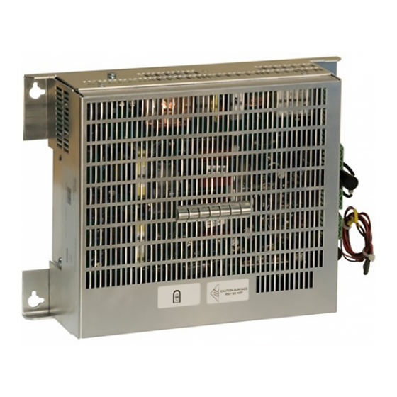
To fit the PSU assembly (A) into the Back Box, proceed as
To fit the PSU assembly (A) into the Back Box, proceed as
follows:
follows:
1 Place one of the nylon spacers (B) supplied in the kit over
1 Place one of the nylon spacers (B) supplied in the kit over
each of the four larger stand-offs (C) on the rear wall of the
each of the four larger stand-offs (C) on the rear wall of the
Back Box, then screw one of the M4 x 16 SEM screws (D)
Back Box, then screw one of the M4 x 16 SEM screws (D)
approximately 2 or 3 rotations into each stand-off - DO NOT
approximately 2 or 3 rotations into each stand-off - DO NOT
FULLY TIGHTEN.
FULLY TIGHTEN.
'A'
2 Hang the PSU assembly (A) over the screws - orientate it so
2 Hang the PSU assembly (A) over the screws - orientate it so
that the mains socket (E) is to the right - then fully tighten the
that the mains socket (E) is to the right - then fully tighten the
E
screws.
screws.
3 Refer to PSU wiring instructions overleaf.
3 Refer to PSU wiring instructions overleaf.
VIEW
A
NOTE:
Access to components inside the safety cover of the PSU7A is
not required for installation and commissioning purposes.
There is no need to remove the safety cover to replace any
fuses, as with earlier versions of the PSU7A, as these are
located on the PCB outside the cover.
1
by Honeywell
997-277-000-9, Issue 9 February 2010
Advertisement
Table of Contents

Related Manuals for Honeywell Notifier PSU7A


Summary of Contents for Honeywell Notifier PSU7A
- Page 1 Honeywell Installing the Kit PSU7A Assembly The Kit PSU7A Assembly (PN: 020-579) is simple to fit to an ID2000/3000 Series Extended Deep Back Box or in a Remote The Kit PSU7A Assembly (PN: 020-579) is simple to fit to an ID2000/3000 Series Extended Deep Back Box or in a Remote Battery/PSU Enclosure, providing the instructions described below are followed.
- Page 2 Installing the Kit PSU7A Assembly in a Back Box (Continued) Installing the Kit PSU7A Assembly in a Back Box (Continued) Wiring Connections Fuses Connect the wiring to the PSU as follows: Fuse ID Type 1 Connect the PSU Charger Inhibit wiring between the F200 T 10A H Charger Inhibit connector (i) and the DTP/Booster module,...
- Page 3 Installing the Kit PSU7A Assembly in a Back Box (Continued) Mains and Safety Earth Wiring Note: All blade connections to earth Connections incorporate a locking barb. To make a connection push the shrouded receptacle on to the earth blade (1). To WARNING.
- Page 4 Installing the Kit PSU7A Assembly in a Remote Enclosure IMPORTANT NOTE IMPORTANT NOTE If the PSU7A is used in the remote battery If the PSU7A is used in the remote battery enclosure the enclosure must be mounted in close enclosure the enclosure must be mounted in close association with the cie.
- Page 5 Installing the Kit PSU7A Assembly in a Remote Enclosure (Continued) Wiring Connections When mounting the PSU7A in an external battery box, the following supplied cables are not required: a) The orange and green wires. (ii) b) The red and black wires. c) The ribbon cable with attached ferrite.
- Page 6 Installing the Kit PSU7A Assembly in a Remote Enclosure (Continued) Mains and Safety Earth Wiring Connections IF PSU7A IS A REPLACEMENT FOR 'OLD' VERSION WITH INTEGRAL WARNING. Risk of electric shock. Before working MAINS LEAD: Remove the existing mains terminal block and use its on mains connections, ensure the mains power screw to fit terminal block of mains cable PN: 082-254-001 in its place.
- Page 7 Installing the Kit PSU7A Assembly (Continued) PSU7A Specifications The PSU may be mounted in the ID3000 Series Back Box or mounted in an external battery box. When the PSU7A is mounted in an external battery box there are three charging configurations set by links on the PSU7A (refer to previous page for details).
Need help?
Do you have a question about the Notifier PSU7A and is the answer not in the manual?
Questions and answers