Table of Contents
Advertisement
Available languages
Available languages
Advertisement
Chapters
Table of Contents

Related Manuals for Vissani QR254 Series


Summary of Contents for Vissani QR254 Series
- Page 1 Under Cabinet Range Hood Campana extractora para in- stalación bajo gabinete # QR254 (SERIES) IMPORTANT / IMPORTANTE Additional parts located inside range hood. Piezas adicionales ubicadas dentro de la campana extractora. Owner’s Manual Manual del usario Rev. 20221101...
-
Page 2: Table Of Contents
Table of Contents Safety Information ........2 Maintenance Warranty Replacing Filters . - Page 3 Use an extinguisher only if: (a) you have a class ABC your back to the exit. CLEANING SAFETY INFORMATION kept free from accumulation of cooking residue. Old and worn 2. Never disassemble parts to clean. Parts should be disassembled Please contact vissani@conglom.com or 1-888-449-9197...
-
Page 4: Warranty
Vissani warrants this product to be free from defects in materials or workmanship for one (1) year from the date of purchase. Proof of purchase (original sales receipt) from the original consumer purchaser must be made available to Vissani for all warranty claims. -
Page 5: Pre-Installation
Pre-Installation TOOLS/MATERIALS REQUIRED (NOT SUPPLIED) Measuring tape Level Utility knife Adjustable Pencil Duct Tape wrench Flathead Needle nose Phillips screwdriver screwdriver pliers Hammer Electric drill Safety goggles Safety gloves Please contact vissani@conglom.com or 1-888-449-9197... -
Page 6: Package Contents
Pre-Installation (continued) PACKAGE CONTENTS Carefully check the range hood for damage and for missing parts prior to installation. If there is any damage or if you are missing parts, with your new range hood. Components D - H Inside Range Hood Part Description Quantity Range hood... -
Page 7: Planning Installation
4.5” (188mm) 0.25” (6.4mm) 0.8” (20mm) (115mm) 3.58” (91mm) 3.58” DIA.1.26" (91mm) (32mm) 0.94" (24mm) DIA.1.26" 2.12” (54mm) 10.25" (260mm) (32mm) 10.25" 11.2” (285mm) (260mm) Fig. 3: Top Venting Option Fig. 4: Back Venting Option Please contact vissani@conglom.com or 1-888-449-9197... - Page 8 Pre-Installation (continued) Your venting system must vent to the outdoors either horizontally through the back wall (13) or vertically through the roof (14) (refer to Fig. 5/Fig. 6/Fig. 7). Use round metal duct work with a uniform diameter of 7 in (177 mm). The total duct run in the venting system should not be more than 35 ft (10.7 m).
- Page 9 When cutting or drilling into the wall or ceilling, do not damage electrical wiring and other hidden utilities. Wire size must conform to all local codes and ordinances. The latest edition requirements of the National Electrical Code ANSI/ WHITE WIRES GREEN GROUND SCREW BLACK WIRES Please contact vissani@conglom.com or 1-888-449-9197...
-
Page 10: Installation
Installation WARNING: FUEL (GAS) BURNING RANGES MUST BE VENTED OUTDOORS USING, AT MINIMUM, METAL DUCTWORK AND RANGE HOODS OF SUFFICIENT CAPACITY. Follow your fuel burning equipment manufacturer’s guidelines, as well as, all applicable safety standards published by the National Fire Protection Association (NFPA), and the American Society for Heating, Refrigeration and Air Conditioning Engineers (ASHRAE), and your local code authorities. - Page 11 Refer to the marking on brackets to determine the correct installation side and orientation. Flat end of the bracket with the arrow should face towards Fig. 16 you and the notched end should face the wall. Please contact vissani@conglom.com or 1-888-449-9197...
- Page 12 Installation (continued) Center Line Align the bracket against the side edge of the 30 in (762 mm) cabinet cabinet and the back wall. Draw a line 15 in (381 mm) Slide the bracket inwards and align it against the marked Fig.
- Page 13 18mm wood screws (AA). If a given mounting hole instead. 7/64” Fig. 19-2 Repeat the above procedure to install the remaining framed cabinet bracket on the opposite side of the cabinet. Fig. 19-3 Please contact vissani@conglom.com or 1-888-449-9197...
- Page 14 Installation (continued) SECURING THE RANGE HOOD TO THE BRACKETS NOTE: The following procedure applies to both frame or frameless cabinet bracket installations. There are 2 pairs of recessed slots in the front and rear of the range hood. Rear (R) slots can be used to hold the range hood vent and electrical connections.
- Page 15 Grease Shield Restore the power to the range hood and ensure that the Fig. 23 lights and fan are operating correctly. Please contact vissani@conglom.com or 1-888-449-9197...
- Page 16 Installation (continued) INSTALLING THE CHARCOAL FILTER (SKIP THIS STEP IF YOU ARE USING EXTERIOR VENTING) NOTE: QR254 (SERIES)
-
Page 17: Operation
[Low Speed (4), Medium Speed (3), High Speed (2)] to select the desired level of power. Once a button is pressed, the previous speed mode will be cancelled. Press the power switch (5) to turn off the fan. Please contact vissani@conglom.com or 1-888-449-9197... -
Page 18: Maintenance
Maintenance REPLACING CASSETTE FILTER Turn off the power circuit breaker or the power switch on the junction box before performing maintenance. Touching circuitry inside the range hood while it is energized will result in death or serious injury. installations and should be replaced periodically (approximately every 3 to 6 months), depending on frequency of use. -
Page 19: Care And Cleaning
Please contact vissani@conglom.com or 1-888-449-9197... -
Page 20: Troubleshooting
Troubleshooting Turn off the power circuit breaker or the power switch on the junction box before performing maintenance. Touching circuitry inside the range hood while it is energized may result in serious injury or death. Problem Solution The range hood does not operate. Check that the power supply cable and all electrical wiring are properly connected. -
Page 21: Wiring Diagram
SERIES 18 in (457 mm) D 1.0A base light bulb Recirculating/ Inside venting 5 in (127 mm) H WIRING DIAGRAM 120V/60Hz BLACK WHITE WHITE BLACK YELLOW/GREEN MOTOR GRAY BLACK BLUE WHITE YELLOW BROWN 2x5W(GU10) 5uF/370V Please contact vissani@conglom.com or 1-888-449-9197... -
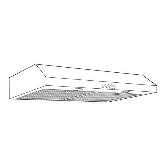
Page 22: External Range Hood Diagram
EXTERNAL DIAGRAM OF RANGE HOOD 29.8 in (758 mm) 27.24 in (692 mm) 8.66 in (220 mm) 1.30 in (33 mm) 13.78 in (350 mm) 0.98 in (25 mm) 1.06 in (27 mm) 3.70 (94 mm) 13.5 in (342.9 mm) 14.92 in (379 mm) 0.59 in (15 mm) 3 in (76.2 mm) -
Page 23: Service Parts
Service Parts If you are missing parts or if you require replacement parts, please contact our customer service team at vissani@conglom.com or 1-888-449-9197 Part Description Code Quantity Rectangular Damper QHR186M Switch QHR187M Bulb Holder QHR223M LED Bulb QHR181M Capacitor QHR188M... -
Page 24: Información De Seguridad
Índice Funcionamiento .........39 OWNER’S MANUAL . - Page 25 2. Nunca desarme las partes que van a limpiarse. Las partes deben Escriba a vissani@conglomkb.com o llame al 1-888-449-9197 entre las 8:30 a. m. y las 5:00 p. m., hora del Este, de lunes a viernes para solicitar más información.
-
Page 26: Garantía
Vissani garantiza este producto contra defectos en materiales y de fabricación durante 1 (un) año a partir de la fecha de compra. Es necesario que el comprador original entregue a Vissani el comprobante de compra (recibo original) para todos los reclamos relacionados con la garantía. -
Page 27: Preinstalación
(Phillips) plano Gafas de Martillo Taladro eléctrico seguridad Guantes de seguridad Escriba a vissani@conglomkb.com o llame al 1-888-449-9197 entre las 8:30 a. m. y las 5:00 p. m., hora del Este, de lunes a viernes para solicitar más información. -
Page 28: Contenido Del Paquete
Preinstalación (continuación) CONTENIDO DEL PAQUETE faltan partes, no prosiga con la instalación. Reporte de inmediato los daños y las partes faltantes. No deseche el empaque antes de que esté satisfecho con su nueva campana de extracción. Componentes dentro de la D - H Campana Extractora Pieza... - Page 29 Fig. 3: Opción para ventilación superior Fig. 4: Opción para ventilación posterior Escriba a vissani@conglomkb.com o llame al 1-888-449-9197 entre las 8:30 a. m. y las 5:00 p. m., hora del Este, de lunes a viernes para solicitar más información.
- Page 30 Preinstalación (continuación) Su sistema de ventilación debe sacar el aire hacia el exterior, ya sea horizontalmente a través de la pared trasera (13) o Utilice un ducto metálico redondo con un diámetro uniforme de 7 pulgadas (177 mm). La extensión total de los ductos en el sistema de ventilación no debe superar los 35 pies (10.7 m).
- Page 31 CABLES Nacional (National Electrical Code) ANSI/NFPA 70 o la última edición NEGROS Escriba a vissani@conglomkb.com o llame al 1-888-449-9197 entre las 8:30 a. m. y las 5:00 p. m., hora del Este, de lunes a viernes para solicitar más información.
-
Page 32: Instalación
Instalación ADVERTENCIA: LAS HORNILLAS DE GAS DEBEN VENTILARSE EN EXTERIORES UTILIZANDO, POR LO MENOS, CONDUCTOS METÁLICOS Y CAMPANAS EXTRACTORAS DE publica la Asociación Nacional de Protección contra Incendios (National Fire Protection Association, NFPA) y la Sociedad Estadounidense de Ingenieros de Calefacción, Refrigeración y Aire Acondicionado (American Society for Heating, Refrigeration and Air Conditioning Engineers, ASHRAE), así... - Page 33 Fig. 16 orientado hacia la pared. Escriba a vissani@conglomkb.com o llame al 1-888-449-9197 entre las 8:30 a. m. y las 5:00 p. m., hora del Este, de lunes a viernes para solicitar más información.
- Page 34 Instalación (continuación) Línea central Alinee el soporte contra el borde lateral de la alacena de 30 pulgadas (762 mm) y de la pared posterior. Dibuje una línea a lo largo del borde interior del soporte, como se 15 pulg (381 mm) Fig.
- Page 35 Fig. 19-3 Escriba a vissani@conglomkb.com o llame al 1-888-449-9197 entre las 8:30 a. m. y las 5:00 p. m., hora del Este, de lunes a viernes para solicitar más información.
- Page 36 Instalación (continuación) CÓMO FIJAR LA CAMPANA EXTRACTORA A LOS SOPORTES NOTA: El siguiente procedimiento se aplica a la instalación de los soportes para las alacenas con marco o sin él. Hay 2 pares de ranuras huecas en la parte frontal y posterior de la campana extractora.
- Page 37 Protector contra la grasa Fig. 23 Escriba a vissani@conglomkb.com o llame al 1-888-449-9197 entre las 8:30 a. m. y las 5:00 p. m., hora del Este, de lunes a viernes para solicitar más información.
- Page 38 Instalación (continuación) INSTALACIÓN DEL FILTRO DE CARBÓN (OMITA ESTE PASO SI ESTÁ UTILIZANDO VENTILACIÓN EXTERIOR) NOTA: QR254 (SERIES)
-
Page 39: Funcionamiento
Presione el interruptor de encendido (5) para apagar el ventilador. Escriba a vissani@conglomkb.com o llame al 1-888-449-9197 entre las 8:30 a. m. y las 5:00 p. m., hora del Este, de lunes a viernes para solicitar más información. -
Page 40: Mantenimiento
Mantenimiento CAMBIO DE FILTRO DE CASSETTE Desconecte el disyuntor de alimentación o apague el interruptor de la caja de derivación antes de realizar el mantenimiento. No toque los circuitos que se encuentran dentro de la campana extractora mientras está mano o en el lavavajillas, utilizando una solución de detergente conectada, pues esto puede ocasionar la muerte o una lesión grave. -
Page 41: Cuidado Y Limpieza
Escriba a vissani@conglomkb.com o llame al 1-888-449-9197 entre las 8:30 a. m. y las 5:00 p. m., hora del Este, de lunes a viernes para solicitar más información. -
Page 42: Solución De Problemas
Solución de problemas Desconecte el disyuntor de alimentación o apague el interruptor de la caja de derivación antes de realizar el mantenimiento. No toque los circuitos que se encuentran dentro de la campana extractora mientras está conectada, pues esto puede ocasionar lesiones graves o la muerte. Problema Solución La campana extractora no funciona. -
Page 43: Diagrama De Cableado
BLANCO NEGRO AMARILLO/VERDE MOTOR GRIS NEGRO AZUL BLANCO AMARILLO MARRÓN 2x5W(GU10) 5uF/370V Escriba a vissani@conglomkb.com o llame al 1-888-449-9197 entre las 8:30 a. m. y las 5:00 p. m., hora del Este, de lunes a viernes para solicitar más información. -
Page 44: Diagrama Externo De La Campana Extractora
DIAGRAMA EXTERNO DE LA CAMPANA EXTRACTORA 29.8 pulg (758 mm) 27.24 pulg (692 mm) SUPERIOR 8.66 pulg (220 mm) 1.30 pulg (33 mm) 13.78 pulg (350 mm) 0.98 pulg (25 mm) 1.06 pulg (27 mm) 3.70 (94 mm) 13.5 pulg (342.9 mm) 14.92 pulg... -
Page 45: Piezas De Refacción
Piezas de refacción Si le faltan piezas o requiere refacciones, escríbale a nuestro equipo de servicio al cliente a vissani@conglom.com o llame al 1-888-449-9197 correspondiente. Pieza Descripción Código Cantidad Regulador rectangular QHR186M Interruptor QHR187M Portalámparas QHR223M Bombilla LED QHR181M Condensador... - Page 46 Questions, problems, missing pieces? Before returning to the store, please contact Customer Service from 8:30 am - 5 pm, EST, Monday - Friday ¿Preguntas, problemas, piezas faltantes? Antes de devolver el producto a la tienda, comuníquese con nuestro equipo de servicio al cliente de 8:30 am.
Need help?
Do you have a question about the QR254 Series and is the answer not in the manual?
Questions and answers
My QR254S stopped working. How do I repair? I do not see instructions in Owner's Manual. Thanks!
To repair a Vissani QR254S that has stopped working, follow these steps:
1. Check Power Supply: Ensure the unit is connected to power and the circuit breaker or junction box switch is turned on.
2. Inspect the Lights:
- If the lights do not work, check if the bulbs are burnt out and replace them.
- If new bulbs do not work, the issue may be with the lamp holder, which may need repair or replacement.
3. Fan Operation:
- Press the appropriate speed control button (Low, Medium, or High) to check if the fan responds.
- If the fan does not turn on, verify the wiring connections and ensure the motor is functioning.
4. Check Components:
- Inspect the capacitor and motor for any signs of damage or failure.
- Replace faulty components as needed.
5. Contact Support:
- If the problem persists, contact Vissani customer service at vissani@conglom.com or call 1-888-449-9197 for further assistance.
Always turn off the power before performing any maintenance or repairs.
This answer is automatically generated