
Related Manuals for Bellfires Smart Bell 80 MF


Summary of Contents for Bellfires Smart Bell 80 MF
- Page 1 Installation and maintenance manual Smart Bell 80/60 MF Serial number: Production date:...
- Page 2 Barbas Bellfires BV. This document could contain technical inaccuracies or typographical errors. Barbas Bellfires BV reserves the right to revise this document from time to time in the contents thereof.
-
Page 3: Table Of Contents
Contents Contents About this document................5 How to work with this document....................5 Warnings and cautions used in this document................5 Related documentation........................ 5 Description....................6 Intended use..........................6 Installation options........................6 Overview of a typical installation....................6 Overview of the appliance......................7 Overview of the burner bed and the pilot light................ - Page 4 Contents 5.2.2 Install the door (including glass)..................27 5.2.3 Remove the frame......................28 5.2.4 Install the frame.......................29 5.2.5 Clean the glass....................... 29 5.2.6 Replace the ambient light bulb when broken..............29 Troubleshooting..................30 Technical specification................31 Smart Bell 80/60 MF (MagniFire) - GB, IE, ES, IT..............31 Diagram electricity and gas......................33 Dimensions Smart Bell 80/60 with a Built-in frame..............
-
Page 5: About This Document
About this document About this document This document shows the necessary information to do these tasks on the Smart Bell 80/60 MF: • Installation • Maintenance This document refers to the Smart Bell 80/60 MF as 'the appliance'. This document is an essential part of your appliance. -
Page 6: Description
Description Description Intended use The appliance is intended for use in a completely sealed or mechanically ventilated house without extra ventilation and/or fume extraction to heat the room wherein it is installed. Do not use it for other purposes. The appliance may only be used at a location that meets the requirements for the installation of the appliance. -
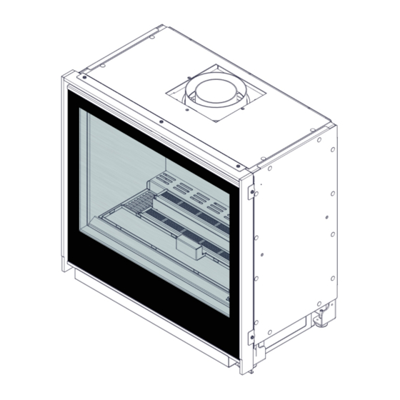
Page 7: Overview Of The Appliance
Description Item Description Appliance Decorative gas fire that heats the room Control unit Contains the gas regulator block, receiver and the fan/light module Inlet grate Provides the fireplace with air Outlet grate The heated air in the fireplace is extracted by the outlet grates into the room Concentric flue system (wall outlet variant) The concentric flue system provides combus-... -
Page 8: Overview Of The Burner Bed And The Pilot Light
Description Item Description Overpressure door Protects the appliance against an overpres- sure Control unit Contains the gas regulator block, receiver and the fan/light module Convection casing Collects the heated convection air. The con- vection air has a natural upward flow and is extracted by the upper front side openings of the appliance Convection fan set (option) -
Page 9: Overview Of The Ceramic Log Set
Description Overview of the ceramic log set No. Ember grate No. Ember grate No. Ember grate with pilot opening No. Ember grate No. 'Fire glass' Dark Amber No. 'Fire glass' Black No. Embers No. Charcoal Smart Bell 80-60... - Page 10 Description No. Charcoal No. Charcoal No. Log No. Log No. Wood chip No. Wood chip Smart Bell 80-60...
-
Page 11: Overview Of The Control Elements
Description No. Wood chip No. Wood chip Overview of the control elements 2.7.1 Overview of the rear of the gas regulator block Item Description Inlet pressure tap Point to measure the gas supply pressure Outlet pressure tap Point to measure the front burner pressure Gas supply connection The connection for the gas supply pipe Gas connection for the front burner... -
Page 12: Overview Of The Front Of The Gas Regulator Block
Description 2.7.2 Overview of the front of the gas regulator block Description Pilot gas adjustment screw Sets the pilot light gas pressure. The adjust- ment screw is factory set and sealed. Adjustment screw maximum burner pressure Sets the maximum gas pressure for the burn- er. -
Page 13: Overview Of The Connections On The Gas Regulator Block
Description 2.7.3 Overview of the connections on the gas regulator block Item Description Pilot light pipe Supplies gas to the pilot light burner Thermocouple Detects if the pilot light is on Connector (nut-olive) Ø 4mm Connects the pilot light gas pipe to the gas regulator block Thermocouple interrupter Interrupts the signal of the thermocouple, and... -
Page 14: Overview Of The Receiver
Connection for a wifi-box (SI) Optionally, a wifi-box can be connected to the receiver to control the appliance with a smart- phone or tablet with the Bellfires app. Connection for the fan/light module (MOD- To control the light function and optionally to... -
Page 15: Overview Of The Fan/Light Module
Description 2.7.5 Overview of the fan/light module Item Description connection for the power supply Connection for the 230 VAC power cable with an earthed plug. Connection is also used for earthing the appliance Connection for a convection fan Powers the convection fan. Optional for this appliance Connection for the ambient lights Powers the ambient light bulbs... -
Page 16: Safety
Safety Safety Safety devices on the appliance Name Description Thermo-electric pilot light shut off Prevents unforseen discharge of gas from the main burner. Overpressure door If an overpressure occurs in the appliance, the door opens for a short duration. When the door opens, a loud noise can occur. -
Page 17: Safety Instructions With Regard To The Environment
Safety Caution: • Only use the items that are supplied or described in the preparation manual and other related documentation. • Do not use masking tape on the appliance. Masking tape can damage the finish of the appliance. • Do not insulate the appliance. If necessary, only install strips of white, loose insulation wool that is heat resistant up to at least 1000 °C. -
Page 18: Installation
Installation Installation Installation prerequisites Make sure that the location agrees with the requirements. Refer to the preparation manual. Make sure that the details of the rating plate of the appliance agree with the gas type and gas pressure of the gas supply. Installation procedure Note: The appliance is factory set to the correct nominal heat input. -
Page 19: Horizontally Align The Appliance
Installation 4.2.2 Horizontally align the appliance • Adjust the adjustable feet. Use an hexagonal key of size 4. Make sure that distance x is at least 1 cm. Make sure that the appliance is installed horizontally. 4.2.3 Make the gas connection Caution: •... -
Page 20: Connect The Concentric Flue System
Installation 4.2.6 Connect the concentric flue system Connect the concentric flue system to the appliance. Use the materials that are specified in the preparation manual. Do not use any other materials. Make sure that all mechanical connections of the concentric flue system are correctly connected. -
Page 21: Build The Fireplace
Installation Baffle plate has been removed. (The use of a restriction plate, without a baffle plate, is not allowed.) 4.2.9 Build the fireplace Safety conditions Caution: 5.2.1 • Remove the door (including glass). See • Remove the frame to prevent damage of the frame during work. See 5.2.3 •... -
Page 22: Do A Check On The Operation Of The Lighting
Installation 4.3.1 Do a check on the operation of the lighting • Make sure that the operation of the ambient lights function well. To operate the lights with the remote control, refer to the user manual 4.3.2 Put the ceramic log set on the burner bed Safety conditions Warning: •... - Page 23 Installation Spread the fire glass -dark amber- evenly on the metal grate in front of the burner bed. Spread the fire glass -black- evenly on the metal grate on the left (L) and right (R) of the burner bed. Note: Set the light intensity of the ambient lighting to maximum on the remote control.
-
Page 24: Do A Final Check On The Fireplace
Installation Put the logs and chips of wood on the burner bed. Refer to for the numbers of the items. 5.2.2 Install the door (including glass.) Refer to 4.3.3 Do a final check on the fireplace Safety conditions Caution: Wait 4 weeks after the installation before you use the fireplace. The cement needs to harden. -
Page 25: Maintenance
• Do all procedures in this section every year. Caution: • Use only original parts. Individual parts for replacement or accessories are available from your BELLFIRES-dealer. • Introduced modifications to the appliance are not permitted. 5.1.1 Clean the appliance Safety conditions Caution: •... -
Page 26: Do A Check On The Appliance
Maintenance 5.1.2 Do a check on the appliance 4.2.4 Do a check for leaks on the gas pipes and the gas pipe connections. Refer to Make sure that the pilot light operates correctly. The pilot light must not show any anomalies. -
Page 27: Install The Door (Including Glass)
Maintenance Dismantle the safety strip from the door. Caution: When loosening the door and after it has been loosened, support it with your hand to prevent it falling forward ! Carefully tilt the door and the glass forwards at the top. Prevent damage by laying paperboard on the chimney breast, under the door. -
Page 28: Remove The Frame
Maintenance With the hook, pull the thin, metal spring strips on the top left and right on the studs of the door. Caution: • Make sure whether the door is properly positioned underneath in the 2 holes of the front. •... -
Page 29: Install The Frame
Maintenance 5.2.4 Install the frame Push the frame on the appliance. Tighten the 3 hexagonal bolts on the inside of the top frame and the 2 Hexagonal bolts at the bottom left and bottom right (A) respectively. Make sure that the frame connects well to the wall. -
Page 30: Troubleshooting
Troubleshooting Troubleshooting Problem possible cause solution The main fire stops to burn The concentric flue system is Install the concentric flue sys- not installed according to the tem correctly. Refer to the specified instructions. preparation manual. An incorrect flue gas restriction Install the correct gas restric- 4.2.7 plate is fitted. -
Page 31: Technical Specification
Technical specification Technical specification Smart Bell 80/60 MF (MagniFire) - GB, IE, ES, IT Natural gas Butane/ Propane Name Bellfires Bellfires Model Smart Bell 80/60 MF Smart Bell 80/60 MF Country GB, IE, ES, IT GB, IE, ES, IT Product identification no... - Page 32 Technical specification Natural gas Butane/ Propane Pilot light burner injector no 36 (SIT 0.977.091) no 23 (SIT 0.977.150) Gas connection 3/8” G / Ø12 mm 3/8” G / Ø12 mm Concentric flue system connec- Ø100 mm - Ø150 mm Ø100 mm - Ø150 mm tion Batteries remote control receiv- None...
-
Page 33: Diagram Electricity And Gas
Technical specification Diagram electricity and gas Item Main burners Gas regulator block Gas valve of the rear burner Receiver Fan/Light module Ambient lighting Gas pipe rear burner Gas pipe front burner Gas supply connection Pilot light burner Pilot light pipe Piezo cable Thermocouple Thermocouple interrupter... -
Page 34: Dimensions Smart Bell 80/60 With A Built-In Frame
Technical specification Dimensions Smart Bell 80/60 with a Built-in frame Smart Bell 80-60... -
Page 35: Dimensions Smart Bell 80/60 With A Classic Frame 35 Mm
Technical specification Dimensions Smart Bell 80/60 with a Classic frame 35 mm Smart Bell 80-60... -
Page 36: Dimensions Smart Bell 80/60 With A Classic Frame 52 Mm
Technical specification Dimensions Smart Bell 80/60 with a Classic frame 52 mm Smart Bell 80-60... -
Page 37: Dimensions Smart Bell 80/60 With A Classic Frame 70 Mm
Technical specification Dimensions Smart Bell 80/60 with a Classic frame 70 mm Smart Bell 80-60... -
Page 38: Dimensions Smart Bell 80/60 With An Insert Frame 15 Mm
Technical specification Dimensions Smart Bell 80/60 with an Insert frame 15 mm Smart Bell 80-60... -
Page 39: Dimensions Smart Bell 80/60 With An Insert Frame 50 Mm
Technical specification Dimensions Smart Bell 80/60 with an Insert frame 50 mm Smart Bell 80-60... -
Page 40: Dimensions Smart Bell 80/60 With An Insert Frame 50 Mm And Convection Fan
Technical specification Dimensions Smart Bell 80/60 with an Insert frame 50 mm and Convection fan 7.10 Dimensions of the restriction plate Width of the delivered flue restriction plates in mm Concentric flue connection Ø100 - Ø150 Roof-mounted outlet Smart Bell 80-60... -
Page 41: Warranty Terms
Complaints will only be accepted if they are reported to the Bellfires dealer, together with the serial number of the Bellfires appliance which is stated on the front of the user manual. In addition, the original receipt (invoice, receipt, cash receipt) showing the date of purchase must also be submitted. - Page 42 Article 5: Warranty period This warranty will only be granted during the warranty period. The body of the Bellfires appliance is guaranteed for a period of 10 years against construction and/or material faults, starting from the moment of purchase. For other parts of the Bellfires appliance, a similar warranty applies from the moment of purchase for a period of one year.
-
Page 43: Eu-Declaration Of Conformity
EU-Declaration of Conformity EU-Declaration of Conformity Smart Bell 80-60... - Page 44 Your Bellfires dealer 002 - 12.02.2018 - 346398...
Need help?
Do you have a question about the Smart Bell 80 MF and is the answer not in the manual?
Questions and answers