Table of Contents
Advertisement
Quick Links
Advertisement
Table of Contents

Subscribe to Our Youtube Channel
Related Manuals for Diamond 300/TLV


Summary of Contents for Diamond 300/TLV
- Page 1 11/2013 Mod: 300/TLV Production code: 15302C2R02IHL...
- Page 2 Professional slicers CE VERTICALE GTT 250-275-300 BS1 / VCO Operating and Maintenance Manual...
- Page 3 INTRODUCTION This manual has been re-presented to provide the Client with all the information on the machine and its safety regulations, and also the use and maintenance instructions which permit using the machine in the best way and maintaining its efficiency throughout time.
- Page 4 CHAP. 6 - ROUTINE CLEANING page 22 - GENERALITIES - CLEANING THE MACHINE 6.2.1 - Cleaning the goods holder plate 6.2.2 - Cleaning the blade, the bladeguard and the ring 6.2.3 - Cleaning the sliceguard 6.2.4 - Cleaning the sharpener - SLIDE GUIDES LUBRICATION CHAP.
- Page 5 CHAP. 1 - RECEIVING THE MACHINE 1.1 - PACKAGE The slicer is shipped in a package which consists of (Fig. n°1): cardboard box, wooden pallets and protective nylon. They should be disposed of separately and according to the norms in force in the country of installation. Dimensions Gross AxBxC...
- Page 6 Do not expose the package to humidity or rain (Fig. n°4). Fig. n°4 Heavy package. Do not lift manually unless with help of at least three people (Fig. n°5). Fig. n°5 Move the package only by electrical trolleys or manually, equipped with lifting straps (Fig.
-
Page 7: Chap. 2 - Installation
the documents, make a precise report on the damage to the machine. Do not overturn the package!! When transporting it make sure that it is firmly held by the four corners (keeping it parallel to the floor). CHAP. 2 - INSTALLATION WARNING! All operations must be carried out by specialized personnel (Fig. - Page 8 2.2 - POSITIONING Position the pallet, with the slicer, on a flat surface and take off (a) the cap from the slicer (Fig. n°12). At this point turn the machine on its side (Fig. n°13) and unscrew, with the Fig. n°12 Fig.
-
Page 9: Electrical Connection
2.3 - ELECTRICAL CONNECTION Check that the data reported on the technical-part number plate (Fig. n°18), in the delivery documents, correspond in the right order; contact the supplier for clarification if they do not. At this point make sure that the system is standard and that the cable and grounding system perfectly operate. - Page 10 2.3.4 - Slicer with 230 V. three-phase motor The slicer is equipped with a feeding cable with a section area of 5x1mm²; length 1.5m and a blue 15A 3F + T CEI plug. Connect the slicer 230 V. - 50 Hz three-phase supply mains, interposing a magnetothermic differential switch of 10A,= 0.03A.
- Page 11 2.4.1 - 115 V. tension selection 2.4.2 - Single-phase 230 V. tension selection OUTPUT DIAGRAM 2.4.3 - Three-phase 230 V. tension selection 2.4.4 - Three-phase 400 V. tension selection...
- Page 12 2.5 - PRELIMINARY CHECK Before testing make sure the goods holder plate is well-blocked, after which test functioning with the following procedure: “OFF” button Push the “ON” push-button and the “OFF” push-button Fig. n°22; check if by unscrewing the blade guard tie rod the machine stops working;...
- Page 13 The slicer must only be used by trained personnel who know the safety norms contained in this manual perfectly. In the case of an alteration in personnel, give time for training. Do not allow the slicer to be used by children or by untrained people (Fig.
- Page 14 Do not pull the slicer or the feeding cable (Fig. n°29) to unplug it. Regularly check the state of the fee- ding cable; a worn out cable or in any ca- se not intact represents a serious electrical danger. ...
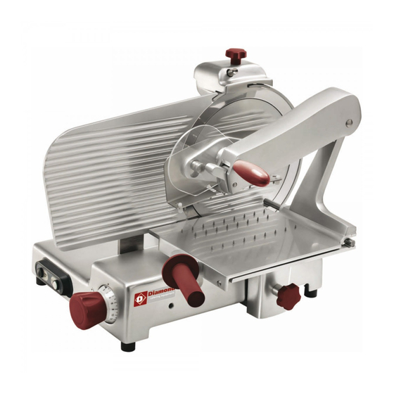
- Page 15 LEGEND: 1 - Cap 14 - Ring 2 - Bladeguard tie rod hand grip 15 - Cap hand grip 3 - Thickness gauge plane 16 - Goods presser hand grip 4 - Base 17 - Sliding plate 5 - Foot 18 - Goods presser handguard 6 - Push-button panel 19 - Plate hand grip...
-
Page 16: Safety Devices Installed On The Machine
4.2 - SAFETY DEVICES INSTALLED ON THE MACHINE 4.2.1 - Mechanical safety As far as mechanical safety is concerned, the slicer described in this manual responds to: CEE 2006/42 machine directives. Safety is made possible by the: - Bladeguard (ref. n°1) - Ring (ref. -
Page 17: Description Of The Machine
- A relay in the control circuit, that re- quires the machine to start up again in case of an accidental loss of electri- city (Fig. n°34). Relay in circuit Fig. n°34 Even though the professional CE slicers are equipped with the standard mea- sures for electrical and mechanical protection (both while operating and during cleaning and maintenance), RESIDUAL RISKS which cannot be completely eli- minated in any case exist, highlighted in this manual under the form of WAR-... - Page 18 TAB. n°1 - DIMENSION MEASUREMENTS AND TECHNICAL FEATURES MODEL U.m. GTT 250 VCO GTT 275 VCO GTT 300 VCO Blade diameter 425 x 320 425 x 320 425 x 320 CxDxE 550 x 590 x 435 560 x 590 x 450 580 x 590 x 460 FxDxG 640 x 590 x 475...
- Page 19 TAB. n°2 - DIMENSION MEASUREMENTS AND TECHNICAL FEATURES MODEL U.m. GTT 250 BS1 GTT 275 BS1 GTT 300 BS1 Blade diameter 425 x 320 425 x 320 425 x 320 CxDxE 550 x 540 x 435 560 x 540 x 450 580 x 540 x 460 FxDxG 790 x 540 x 550...
- Page 20 CHAP. 5 - MACHINE USE 5.1 - OPERATIONAL CHECK For the 1° use follow these instructions: check that installation has been car- ried out correctly as in chapter 2; check that the hopper is well fastened with the lock hand grip (Fig. n°36 ref.1);...
-
Page 21: Loading And Cutting The Product
5.2 - LOADING AND CUTTING THE PRODUCT WARNING: The goods to be cut are loaded on the hopper only with the gradua- ted hand grip at “0” and the motor stopped, being careful with the blade and the points. Adhere to the following procedure: 1. -
Page 22: Sharpening The Blade
or rough surface, therefore thecutting effort increases (chapter 5.3). 5.3 - SHARPENING THE BLADE WARNING: Before starting to sharpen the blade, pay attention to RESI- DUAL RISKS (chapter 4.2.2) concerning the dangers of cutting without ha- ving followed the instructions listed below. To sharpen the blade, which needs to be done periodically as soon a decrease in cutting is noticed, the following directions must be adhered to: 1. - Page 23 7. press the 2 push-buttons (2 and 3) contemporaneously for 3/4 sec. and release them in the same instant (Fig. n°46); 8. after having completed the sharpe- ning it is advisable to clean the grin- ders and the blade (chapter 6.2.3); 9.
- Page 24 having taken off the trolley, the goods holder plate can be carefully cleaned with warm water, the equipped deter- gent or neutral detergent (pH 7). Fig. n°48 6.2.2 - Cleaning the blade, the bladeguard and the ring WARNING: a pair of metallic gloves must be worn while cleaning the bla- de (1) (Fig.
- Page 25 6.2.3 - Cleaning the sliceguard (Fig. n°52) To remove the sliceguard simply grasp the hand grip (1) and pull up so that the two pins unhook (2), and then extract the sliceguard. At this point clean the sliceguard with warm water, the equipped detergent or Fig.
-
Page 26: Chap. 7 - Maintenance
CHAP. 7 - MAINTENANCE 7.1 - GENERALITIES Before carrying out any maintenance operations it is necessary to: a) disconnect the feed plug from the electrical network to completely isolate machine from the rest of the system. b) bring the graduated hand grip which regulates the thickness gauge to “0”. 7.2 - BELT The belt does not need to regulated. -
Page 27: Chap. 8 - Dismantling
CHAP. 8 - DISMANTLING 8.1 - OUT OF SERVICE If for some reason it is decided to put the machine out of service, make sure that it cannot be used by anyone: detach or cut the electrical connections. 8.2 - WEEE Waste of Electric and Electronic Equipment Directive 2002/95/EC, 2002/96/EC and 2003/108/EC on the restriction of the use of certain hazardous substances in electrical and electronic equipment, and waste electrical and electronic equipment...
Need help?
Do you have a question about the 300/TLV and is the answer not in the manual?
Questions and answers