
Subscribe to Our Youtube Channel
Related Manuals for Micsig SigOFIT MOIP01P SigOFIT MOIP01P


Summary of Contents for Micsig SigOFIT MOIP01P SigOFIT MOIP01P
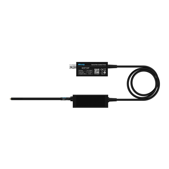
- Page 1 SigOFIT Optical-fiber Isolated Probe Quick Guide Shenzhen Micsig Technology Co., Ltd. Scan to watch Youtube video www.micsig.com...
- Page 2 WARNING DO NOT block the heat dissipation port on the back of Optical-Electrical converter, otherwise the probe may be overheated and damaged. DO NOT excessively bend the fiber cable. Avoid tight radius (<8cm) bends, crushing, crimping, twisting, pulling or otherwise stressing the cable. SigOFIT™...
- Page 3 Main Steps: 1. Connect the Optical-Electrical (O-E) converter to oscilloscope (Figure 1); O-E Converter Figure. 1 2. Set the oscilloscope input impedance to 50Ω, set corresponding attenuation ratio and delay time on the oscilloscope; Connect attenuating tip to the Electrical–Optical (E-O) converter (Figure 2); Figure.
- Page 4 4. Power the SigOFIT probe by connecting USB-C cable to O-E Converter using standard charger (localized) (Figure 3); Figure. 3 5. Solder the MCX connector to the test board: 1) When testing Vgs signal, the signal pin (in the middle) of the MCX female connector must be connected to the G-end of the MOSFET;...
- Page 5 * Always press Cali. button to get better results before get final test readings. ② “△” / “▽”: Press to adjust offset position manually (normally not required). * Please refer to User Manual or contact Micsig for more information. Email: sales@micsig.com Tel: +86-755-88600880...
Need help?
Do you have a question about the SigOFIT MOIP01P SigOFIT MOIP01P and is the answer not in the manual?
Questions and answers