Table of Contents
Advertisement
Quick Links
ACEGU
INSTALLATION, OPERATION,
AND MAINTENANCE MANUAL
JS4D20−E9.4 230V 3P
JS4D20−E9.4 230V 3P
JS4D20−E9.4 230V 3P
THE GORMAN-RUPP COMPANY D MANSFIELD, OHIO
GORMAN-RUPP OF CANADA LIMITED
WITH PARTS LIST
80 SERIES PUMPS
MODELS
MODEL
83A2−GX240
www.gormanrupp.com
D
ST. THOMAS, ONTARIO, CANADA
e
Copyright by the Gorman-Rupp Company
February 5, 1991
Rev. A 08-26-04
JS4D20−E9.4 230V 3P
JS4D20−E9.4 230V 3P
JS4D20−E9.4 230V 3P
Printed in U.S.A.
OM-03581-01
Advertisement
Table of Contents

Related Manuals for GORMAN-RUPP PUMPS 83A2-GX240


Summary of Contents for GORMAN-RUPP PUMPS 83A2-GX240
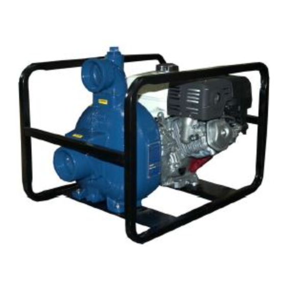
- Page 1 ACEGU OM-03581-01 February 5, 1991 Rev. A 08-26-04 INSTALLATION, OPERATION, AND MAINTENANCE MANUAL WITH PARTS LIST 80 SERIES PUMPS MODELS MODEL JS4D20−E9.4 230V 3P JS4D20−E9.4 230V 3P 83A2−GX240 JS4D20−E9.4 230V 3P JS4D20−E9.4 230V 3P JS4D20−E9.4 230V 3P JS4D20−E9.4 230V 3P THE GORMAN-RUPP COMPANY D MANSFIELD, OHIO www.gormanrupp.com GORMAN-RUPP OF CANADA LIMITED...
- Page 2 The engine exhaust from this product contains chemicals known to the State of California to cause cancer, birth defects or other reproductive harm.
-
Page 3: Table Of Contents
TABLE OF CONTENTS INTRODUCTION ..........PAGE I −... - Page 4 TABLE OF CONTENTS (continued) PUMP MAINTENANCE AND REPAIR - SECTION E ....PAGE E − 1 STANDARD PERFORMANCE CURVE ........PAGE E −...
-
Page 5: Introduction
80 SERIES OM−03581 INTRODUCTION Thank You for purchasing a Gorman-Rupp pump. For information or technical assistance on the en- Read this manual carefully to learn how to safely gine, contact the engine manufacturer’s local install and operate your pump. Failure to do so dealer or representative. - Page 6 OM−03581 80 SERIES SAFETY - SECTION A This information applies to 80 Series en- gine driven pumps. Refer to the manual accompanying the engine before at- tempting to begin operation. This pump is designed to handle most non-volatile, non-flammable liquids This manual will alert personnel to containing specified entrained solids.
- Page 7 OM−03581 80 SERIES Overheated pumps can cause severe Fuel used by internal combustion en- burns and injuries. If overheating of the gines presents an extreme explosion pump occurs: and fire hazard. Make certain that all 1. Stop the pump immediately. fuel lines are securely connected and 2.
-
Page 8: Installation − Section B
80 SERIES OM−03581 INSTALLATION − SECTION B Review all Safety information in Section A. to the pump is critical to performance and safety, be sure to limit the incoming pressure to 50% of the Since pump installations are seldom identical, this maximum permissible operating pressure as section offers only general recommendations and shown on the pump performance curve. -
Page 9: Preinstallation Inspection Page B
OM−03581 80 SERIES use lifting equipment with appropriate capacity. PREINSTALLATION INSPECTION Drain the pump and remove all customer-installed equipment such as suction and discharge hoses The pump assembly was inspected and tested be- or piping before attempting to lift existing, installed fore shipment from the factory. -
Page 10: Line Configuration
80 SERIES OM−03581 Line Configuration stalled with the flat part of the reducers uppermost to avoid creating air pockets. Valves are not nor- Keep suction and discharge lines as straight as mally used in suction lines, but if a valve is used, possible to minimize friction losses. -
Page 11: Suction Line Positioning
OM−03581 80 SERIES of the suction pipe. The baffle will allow entrained critical to efficient pump operation. Figure 2 shows air to escape from the liquid before it is drawn into recommended minimum submergence vs. veloc- the suction inlet. ity. If two suction lines are installed in a single sump, the flow paths may interact, reducing the efficiency of one or both pumps. -
Page 12: Bypass Lines
80 SERIES OM−03581 stalled in the discharge line to protect the pump Bypass Lines from excessive shock pressure and reverse rota- If a system check valve is used due to high dis- tion when it is stopped. charge head, it may be necessary to vent trapped air from the top of the pump during the priming process. -
Page 13: Operation − Section C
OM−03581 80 SERIES OPERATION − SECTION C Review all Safety information in Section A. Add liquid to the pump casing when: 1. The pump is being put into service for the Follow the instructions on all tags, labels and first time. decals attached to the pump. -
Page 14: Lines Without A Bypass
OM−03581 80 SERIES line. Air from the suction line will be discharged through the bypass line back to the wet well during the priming cycle. When the pump is fully primed Do not remove plates, covers, gauges, and liquid is flowing steadily from the bypass line, pipe plugs, or fittings from an over- open the discharge throttling valve. -
Page 15: Stopping
OM−03581 80 SERIES Cold Weather Preservation STOPPING Never halt the flow of liquid suddenly. If the liquid being pumped is stopped abruptly, damaging shock waves can be transmitted to the pump and In below freezing conditions, drain the pump to piping system. -
Page 16: Troubleshooting − Section D
80 SERIES OM−03581 TROUBLESHOOTING − SECTION D Review all Safety information in Section A. Before attempting to open or service the pump: 1. Familiarize yourself with this manual. 2. Shut down the engine and discon- nect the spark plug wire to ensure that the pump will remain inopera- tive. - Page 17 OM−03581 80 SERIES TROUBLE POSSIBLE CAUSE PROBABLE REMEDY PUMP STOPS OR Air leak in suction line. Correct leak. FAILS TO DELIVER Lining of suction hose collapsed. Replace suction hose. RATED FLOW OR PRESSURE Leaking or worn seal or pump gasket. Check pump vacuum.
-
Page 18: Preventive Maintenance
80 SERIES OM−03581 equipped) between regularly scheduled inspec- PREVENTIVE MAINTENANCE tions can indicate problems that can be corrected Since pump applications are seldom identical, and before system damage or catastrophic failure oc- pump wear is directly affected by such things as curs. - Page 19 80 SERIES OM−03581 PUMP MAINTENANCE AND REPAIR - SECTION E MAINTENANCE AND REPAIR OF THE WEARING PARTS OF THE PUMP WILL MAINTAIN PEAK OPERATING PERFORMANCE. STANDARD PERFORMANCE FOR PUMP MODEL 83A2−GX240 Based on 70_ F (21_ C) clear water at sea level Contact the Gorman-Rupp Company to verify per- with minimum suction lift.
- Page 20 OM−03581 80 SERIES SECTION DRAWING PARTS PAGE Figure 1. Pump Model 83A2−GX240 PAGE E − 2 MAINTENANCE & REPAIR...
- Page 21 80 SERIES OM−03581 PARTS LIST Pump Model 83A2−GX240 (From S/N 967067 up) If your pump serial number is followed by an N", your pump is NOT a standard production model. Contact the Gorman-Rupp Company to verify part numbers. ITEM PART MAT’L PART NAME NUMBER...
- Page 22 OM−03581 80 SERIES SECTION DRAWING Figure 2. Pump End 83A2−(GX240) PPO PAGE E − 4 MAINTENANCE & REPAIR...
- Page 23 80 SERIES OM−03581 PARTS LIST Pump End 83A2−(GX240) PPO ITEM PART NAME PART MAT’L ITEM PART NAME PART MAT’L NUMBER CODE NUMBER CODE PUMP CASING 6882A 10010 −SMALL VALVE WEIGHT 18 10010 −RD HD MACH SCREW X0403 17090 IMPELLER 6950 10010 −LOCKWASHER 17090...
- Page 24 OM−03581 80 SERIES PUMP AND SEAL DISASSEMBLY 4. Check the temperature before opening any covers, plates, or AND REASSEMBLY plugs. 5. Close the suction and discharge Review all Safety information in Section A. valves. Follow the instructions on all tags, label and de- 6.
- Page 25 80 SERIES OM−03581 pump casing.Tie and tag the gaskets, or measure unit. Remove the grease cup (11) from the interme- and record their thickness for ease of reassembly. diate, and use a suitably sized dowel to press the seal components from the intermediate. Tie and tag any leveling shims used under the cas- ing mounting feet to ease reassembly.
- Page 26 OM−03581 80 SERIES non-oil based solvent and a clean, lint-free tissue. Wipe lightly in a concentric pattern to avoid scratching the faces. Most cleaning solvents are toxic and flammable. Use them only in a well− Inspect the seal components for wear, scoring, ventilated area free from excessive grooves, and other damage that might cause leak- age.
- Page 27 80 SERIES OM−03581 Pump Casing Installation (Figure 2) This seal is not designed for operation at If the wear plate (17) was removed for replace- temperatures above 110_F (43_C). Do not ment, secure it to the pump casing using the at- use at higher operating temperatures.
- Page 28 OM−03581 80 SERIES Install the suction and discharge lines and open all LUBRICATION valves. Make certain that all piping connections are tight, properly supported and secure. Seal Assembly Be sure the pump and engine have been properly (Figures 2 and 4) lubricated, see LUBRICATION.
- Page 29 For U.S. and International Warranty Information, Please Visit www.grpumps.com/warranty or call: U.S.: 419−755−1280 International: +1−419−755−1352 For Canadian Warranty Information, Please Visit www.grcanada.com/warranty or call: 519−631−2870 THE GORMAN-RUPP COMPANY D MANSFIELD, OHIO GORMAN-RUPP OF CANADA LIMITED ST. THOMAS, ONTARIO, CANADA...
Need help?
Do you have a question about the 83A2-GX240 and is the answer not in the manual?
Questions and answers