Table of Contents
Advertisement
Quick Links
COM-01526-02
ACE
November 17, 2005
INSTALLATION, OPERATION,
AND MAINTENANCE MANUAL
WITH PARTS LIST
80 SERIES PUMP
MODEL
84B52-B
THE GORMAN‐RUPP COMPANY D MANSFIELD, OHIO
www.gormanrupp.com
D
GORMAN‐RUPP OF CANADA LIMITED
ST. THOMAS, ONTARIO, CANADA
Printed in Canada.
e
Copyright by the Gorman‐Rupp Company
Advertisement
Table of Contents

Related Manuals for GORMAN-RUPP PUMPS 84B52-B


Summary of Contents for GORMAN-RUPP PUMPS 84B52-B
- Page 1 COM-01526-02 November 17, 2005 INSTALLATION, OPERATION, AND MAINTENANCE MANUAL WITH PARTS LIST 80 SERIES PUMP MODEL 84B52-B THE GORMAN‐RUPP COMPANY D MANSFIELD, OHIO www.gormanrupp.com GORMAN‐RUPP OF CANADA LIMITED ST. THOMAS, ONTARIO, CANADA Printed in Canada. Copyright by the Gorman‐Rupp Company...
-
Page 3: Table Of Contents
TABLE OF CONTENTS INTRODUCTION ..........PAGE I - 1 SAFETY ‐... - Page 4 TABLE OF CONTENTS (continued) PUMP MAINTENANCE AND REPAIR ‐ SECTION E ....PAGE E - 1 PERFORMANCE CURVE ........... PAGE E - 1 PARTS LIST: Pump Model...
-
Page 5: Introduction
80 SERIES OM-01526 INTRODUCTION Thank You for purchasing a Gorman‐Rupp pump. The following are used to alert maintenance per Read this manual carefully to learn how to safely sonnel to procedures which require special atten install and operate your pump. Failure to do so tion, to those which could damage equipment, and could result in personal injury or damage to the to those which could be dangerous to personnel:... -
Page 7: Safety - Section A
80 SERIES OM-01526 SAFETY ‐ SECTION A This information applies to 80 Series ba containing specified entrained solids. Do not attempt to pump volatile or flam sic pumps. Gorman‐Rupp has no con mable liquids which may damage the trol over or particular knowledge of the pump or endanger personnel as a result power source which will be used. - Page 8 OM-01526 80 SERIES Do not operate the pump against a Do not remove plates, covers, gauges, closed discharge valve for long periods pipe plugs, or fittings from an over of time. If operated against a closed dis heated pump. Vapor pressure within the charge valve, pump components will pump can cause parts being disen...
-
Page 9: Installation - Section B
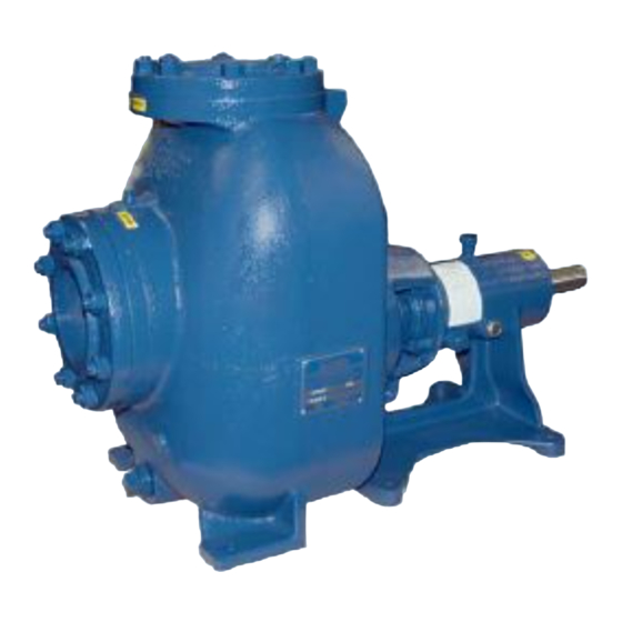
See Figure 1 for the approximate physical dimen specific application. Since the pressure supplied sions of this pump. OUTLINE DRAWING Figure 1. Pump Model 84B52-B INSTALLATION PAGE B - 1... -
Page 10: Preinstallation Inspection
OM-01526 80 SERIES PREINSTALLATION INSPECTION POSITIONING PUMP The pump assembly was inspected and tested be fore shipment from the factory. Before installation, inspect the pump for damage which may have oc Use lifting and moving equipment in curred during shipment. Check as follows: good repair and with adequate capacity a. -
Page 11: Materials
80 SERIES OM-01526 Materials the source of the liquid being pumped; if the line slopes down to the pump at any point along the suction run, air pockets will be created. Either pipe or hose maybe used for suction and discharge lines;... -
Page 12: Suction Line Positioning
OM-01526 80 SERIES If there is a liquid flow from an open pipe into the tance equal to at least 3 times the diameter of the sump, the flow should be kept away from the suc suction pipe. tion inlet because the inflow will carry air down into the sump, and air entering the suction line will re... -
Page 13: Bypass Lines
80 SERIES OM-01526 stalled in the discharge line to protect the pump bolts. The pump casing feet and/or pedestal feet, from excessive shock pressure and reverse rota and the driver mounting bolts should also be tightly tion when it is stopped. secured. -
Page 14: V-Belt Drives
OM-01526 80 SERIES the belts are a matched set; unmatched sets will cause accelerated belt wear. Figure 3B. Aligning Non‐Spider Type Cou plings MISALIGNED: MISALIGNED: ALIGNED: SHAFTS Align non‐spider type couplings by using a feeler SHAFTS SHAFTS PARALLEL AND NOT PARALLEL NOT IN LINE SHEAVES IN LINE gauge or taper gauge between the coupling halves... -
Page 15: Operation - Section C
OM-01526 80 SERIES OPERATION - SECTION C Review all SAFETY information in Section A. 1. The pump is being put into service for the first time. Follow the instructions on all tags, labels and 2. The pump has not been used for a consider decals attached to the pump. -
Page 16: Operation
OM-01526 80 SERIES Consult the operating manual furnished with the filled, adjust the throttling valve to the required flow power source before attempting to start the power rate. source. Leakage If an electric motor is used to drive the pump, re move V‐belts, couplings, or otherwise disconnect No leakage should be visible at pump mating sur... -
Page 17: Pump Vacuum Check
OM-01526 80 SERIES on the pump performance curve (see Section E, Cold Weather Preservation Page 1). In below freezing conditions, drain the pump to prevent damage from freezing. Also, clean out any solids by flushing with a hose. Operate the pump Pump Vacuum Check for approximately one minute;... -
Page 19: Troubleshooting - Section D
80 SERIES OM-01526 TROUBLESHOOTING - SECTION D Review all SAFETY information in Section A. Before attempting to open or service the pump: 1. Familiarize yourself with this manual. 2. Lock out or disconnect the power source to ensure that the pump will remain inoperative. - Page 20 OM-01526 80 SERIES TROUBLE POSSIBLE CAUSE PROBABLE REMEDY Suction intake not submerged at Check installation and correct PUMP STOPS OR FAILS TO DELIVER proper level or sump too small. submergence as needed. RATED FLOW OR Replace worn or damaged parts. Impeller or other wearing parts worn PRESSURE (cont.) Check that impeller is properly...
-
Page 21: Preventive Maintenance
80 SERIES OM-01526 equipped) between regularly scheduled inspec PREVENTIVE MAINTENANCE tions can indicate problems that can be corrected Since pump applications are seldom identical, and before system damage or catastrophic failure oc pump wear is directly affected by such things as curs. - Page 23 MAINTENANCE AND REPAIR OF THE WEARING PARTS OF THE PUMP WILL MAINTAIN PEAK OPERATING PERFORMANCE. STANDARD PERFORMANCE FOR PUMP MODEL 84B52-B Based on 70_ F (21 _ C) clear water at sea level Contact the Gorman‐Rupp Company to verify per...
- Page 24 OM-01526 80 SERIES SECTION DRAWING PARTS PAGE Figure 1. Pump Model 84B52-B PAGE E - 2 MAINTENANCE & REPAIR...
- Page 25 OM-01526 80 SERIES SPECIAL PARTS LIST Pump Model 84B52-B (From Serial Number 1324770 Up) If your pump serial number is followed by an “N”, your pump is NOT a standard production model. Contact the Gorman‐Rupp Company to verify part numbers.
- Page 26 OM-01526 80 SERIES PUMP AND SEAL DISASSEMBLY 4. Check the temperature before opening any covers, plates, or AND REASSEMBLY plugs. 5. Close the suction and discharge Review all SAFETY information in Section A. valves. 6. Vent the pump slowly and cau Follow the instructions on all tags, label and de...
- Page 27 80 SERIES OM-01526 Pump Casing Removal Figure 2. Use caution not to damage the shaft or keyway. When the impeller breaks loose, remove the lathe dog and wood block and unscrew the im To service the impeller (2), wear plate (39) or seal peller from the shaft.
- Page 28 OM-01526 80 SERIES Shaft And Bearing Removal And Disassembly When the pump is properly operated and main tained, the pedestal should not require disassem To prevent damage during removal from bly. Disassemble the shaft and bearings only the shaft, it is recommended that bearings when there is evidence of wear or damage.
- Page 29 80 SERIES OM-01526 If bearing replacement is required, use a bearing After the bearings have been installed and allowed puller to remove the inboard and outboard bear to cool, check to ensure that they have not moved ings from the impeller shaft. out of position in shrinking.
- Page 30 OM-01526 80 SERIES failure. If necessary to reuse an old seal in an emer NOTE gency, carefully wash all metallic parts in fresh Shaft endplay should be .002 to .010 inch (0,05 to cleaning solvent and allow to dry thoroughly. 0,25 mm).
- Page 31 80 SERIES OM-01526 ROTATING O‐RING ELEMENT STATIONARY SEAT SPRING IMPELLER IMPELLER IMPELLER SHAFT ADJUSTING SHIMS SHAFT SLEEVE SPRING SEAL PLATE SEAT BELLOWS RETAINER Figure 3. 25284-961 Seal Assembly until the face of the rotating element is just flush with the chamfered end of the sleeve. Slide the assembled seal and sleeve onto the shaft This seal is not designed for operation at until the seal faces contact.
- Page 32 OM-01526 80 SERIES NOTE Be sure the seal plate is tight against the pedestal while measuring this clearance. Do not attempt to lift the complete pump unit using the lifting eye. It is designed After the back clearance is set, secure the impeller to facilitate removal or installation of in...
- Page 33 80 SERIES OM-01526 Under normal conditions, change the oil each LUBRICATION 5000 hours or once each year, more frequently if the pump is operated continuously or installed in Seal Assembly an environment with rapid temperature change. The seal assembly is lubricated by the medium be ing pumped, and no additional lubrication is re...
- Page 36 For Warranty Information, Please Visit www.grpumps.com/warranty or call: U.S.: 419-755-1280 Canada: 519-631-2870 International: +1-419-755-1352 GORMAN‐RUPP PUMPS...
Need help?
Do you have a question about the 84B52-B and is the answer not in the manual?
Questions and answers