GORMAN-RUPP PUMPS 80 Series Installation, Operation, And Maintenance Manual With Parts List
Hide thumbs
Also See for 80 Series:
Table of Contents
Advertisement
Quick Links
Advertisement
Table of Contents

Related Manuals for GORMAN-RUPP PUMPS 80 Series


Summary of Contents for GORMAN-RUPP PUMPS 80 Series
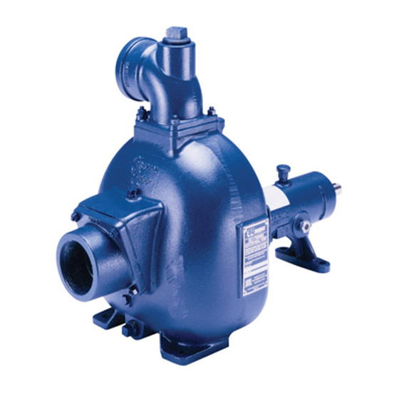
- Page 1 OM−06412−01 April 6, 2011 INSTALLATION, OPERATION, AND MAINTENANCE MANUAL WITH PARTS LIST 80 SERIES PUMP MODEL 84A2−4024H THE GORMAN-RUPP COMPANY D MANSFIELD, OHIO GORMAN-RUPP OF CANADA LIMITED ST. THOMAS, ONTARIO, CANADA Printed in U.S.A. www.grpumps.com 2011 The Gorman-Rupp Company...
- Page 2 Register your new Gorman-Rupp pump online at www.grpumps.com Valid serial number and e-mail address required. The engine exhaust from this product contains chemicals known to the State of California to cause cancer, birth defects or other reproductive harm. RECORD YOUR PUMP MODEL AND SERIAL NUMBER Please record your pump model and serial number in the spaces provided below.
-
Page 3: Table Of Contents
TABLE OF CONTENTS INTRODUCTION ........... PAGE I −... - Page 4 TABLE OF CONTENTS (continued) STANDARD PERFORMANCE CURVE ......... . . PAGE E −...
-
Page 5: Introduction
The following are used to alert maintenance per- pump. sonnel to procedures which require special atten- This pump is an 80 Series, semi-open impeller, self- tion, to those which could damage equipment, and priming centrifugal model with a suction check to those which could be dangerous to personnel: valve. -
Page 6: Safety - Section A
80 SERIES OM−06412 SAFETY − SECTION A This information applies to 80 Series 5. Close the suction and discharge valves. Engine Driven pumps. Refer to the man- 6. Vent the pump slowly and cau- ual accompanying the engine before at- tiously. - Page 7 OM−06412 80 SERIES to a boil, build pressure, and cause the a deadly gas that is colorless, tasteless pump casing to rupture or explode. and odorless. Fuel used by internal combustion en- Do not remove plates, covers, gauges, gines presents an extreme explosion pipe plugs, or fittings from an over- and fire hazard.
-
Page 8: Installation − Section Bpage B
80 SERIES OM−06412 INSTALLATION − SECTION B Review all SAFETY information in Section A. to the pump is critical to performance and safety, be sure to limit the incoming pressure to 50% of the Since pump installations are seldom identical, this... -
Page 9: Battery Specifications And Installation
OM−06412 80 SERIES ing, check for loose hardware at mating sur- POSITIONING PUMP faces. c. Carefully read all tags, decals, and markings on the pump assembly, and perform all duties indicated. Use lifting and moving equipment in d. Check levels and lubricate as necessary. Re-... -
Page 10: Suction And Discharge Piping
80 SERIES OM−06412 consulted for continuous operation at angles SUCTION LINES greater than 15_. To avoid air pockets which could affect pump prim- ing, the suction line must be as short and direct as SUCTION AND DISCHARGE PIPING possible. When operation involves a suction lift, the line must always slope upward to the pump from the source of the liquid being pumped;... -
Page 11: Discharge Lines
OM−06412 80 SERIES Figure 2. Recommended Minimum Suction Line Submergence vs. Velocity DISCHARGE LINES head, gradually close the discharge throttling valve before stopping the pump. Siphoning Bypass Lines Do not terminate the discharge line at a level lower than that of the liquid being pumped unless a si- phon breaker is used in the line. -
Page 12: Operation − Section C
OM−06412 80 SERIES OPERATION − SECTION C Review all SAFETY information in Section A. Add liquid to the pump casing when: 1. The pump is being put into service for the Follow the instructions on all tags, labels and first time. -
Page 13: Operation
OM−06412 80 SERIES OPERATION A Gorman-Rupp automatic air release valve may be installed in a bypass line, or the bypass line may Do not operate the pump against a be left open. closed discharge throttling valve for long periods of time. If operated against... -
Page 14: Strainer Check
OM−06412 80 SERIES Strainer Check If a suction strainer has been shipped with the pump or installed by the user, check the strainer If the application involves a high discharge regularly, and clean it as necessary. The strainer head, gradually close the discharge should also be checked if pump flow rate begins to throttling valve before stopping the pump. -
Page 15: Operation In Extreme Heat
OM−06412 80 SERIES curately by placing a contact-type thermometer the settings. Determine the cause of against the housing. Record this temperature for shutdown before putting the unit back future reference. into service. Consult the factory for ad- ditional information. A sudden increase in bearing temperatures is a... -
Page 16: Troubleshooting − Section D
80 SERIES OM−06412 TROUBLESHOOTING − SECTION D Review all SAFETY information in Section A. to ensure that the pump will remain inoperative. 3. Allow the pump to completely cool if overheated. 4. Check the temperature before opening any covers, plates, or Before attempting to open or service the plugs. - Page 17 OM−06412 80 SERIES Table 1. Trouble Shooting Chart (cont.) TROUBLE POSSIBLE CAUSE PROBABLE REMEDY PUMP STOPS OR FAILS Leaking or worn seal or pump gas- Check pump vacuum. Replace leak- ket. ing or worn seal or gasket. DELIVER RATED FLOW OR PRESSURE (cont.)
-
Page 18: Preventive Maintenance
80 SERIES OM−06412 Table 1. Trouble Shooting Chart (cont.) TROUBLE POSSIBLE CAUSE PROBABLE REMEDY BEARINGS Bearing temperature is high, but Check bearing temperature regularly within limits. to monitor any increase. Low or incorrect lubricant. Check for proper type and level of lu- bricant. - Page 19 OM−06412 80 SERIES Preventive Maintenance Schedule Service Interval* Item Daily Weekly Monthly Semi- Annually Annually General Condition (Temperature, Unusual Noises or Vibrations, Cracks, Leaks, Loose Hardware, Etc.) Pump Performance (Gauges, Speed, Flow) Bearing Lubrication Seal Lubrication (And Packing Adjustment, If So Equipped)
-
Page 20: Pump Maintenance And Repair - Section E
80 SERIES OM−06412 PUMP MAINTENANCE AND REPAIR - SECTION E MAINTENANCE AND REPAIR OF THE WEARING PARTS OF THE PUMP WILL MAINTAIN PEAK OPERATING PERFORMANCE. STANDARD PERFORMANCE FOR PUMP MODEL 84A2−4024H Based on 70_ F (21_ C) clear water at sea level Contact the Gorman-Rupp Company to verify per- formance or part numbers. - Page 21 OM−06412 80 SERIES PARTS PAGE SECTION DRAWING Figure 1. Pump Model 84A2−4024H PAGE E − 2 MAINTENANCE & REPAIR...
- Page 22 80 SERIES OM−06412 Pump Model 84A2−4024H PARTS LIST (From S/N 1488564 Up) If your pump serial number is followed by an N", your pump is NOT a standard production model. Contact the Gorman-Rupp Company to verify part numbers. ITEM PART MAT’L...
- Page 23 OM−06412 80 SERIES SECTION DRAWING NOTE: Generic John Deere Engine Shown Figure 2. 46143−128 John Deere Power Unit Kit PARTS LIST ITEM PART NAME PART MAT’L ITEM PART NAME PART MAT’L NUMBER CODE NUMBER CODE JD 4024H ENGINE 29224−401 −−−...
- Page 24 80 SERIES OM−06412 SECTION DRAWING Figure 3. 46124−403 Pump End Assembly MAINTENANCE & REPAIR PAGE E − 5...
- Page 25 OM−06412 80 SERIES PARTS LIST 46124−403 Pump End Assembly ITEM PART NAME PART MAT’L ITEM PART NAME PART MAT’L NUMBER CODE NUMBER CODE PUMP CASING 7288 10010 BEARING CLOSURE 10010 STUD C0809 15991 IMPELLER 2691D 10010 HEX NUT 15991 SEAL ASSY GS1250 −−−...
- Page 26 80 SERIES OM−06412 SECTION DRAWING Figure 4. 84A2−(SAE 4/10) Drive Assembly ITEM PART MAT’L PART NAME NUMBER CODE COUPLING KIT 48112−001 −−− −BUSHING 24131−345 −−− −COUPLING ASSEMBLY 44165−011 −−− SOCKET HD CAPSCREW BD0606−1/2 15991 SOCKET HD CAPSCREW 22644−220 −−− LOCKWASHER...
- Page 27 OM−06412 80 SERIES PUMP AND SEAL DISASSEMBLY 4. Check the temperature before opening any covers, plates, or AND REASSEMBLY plugs. 5. Close the suction and discharge Review all SAFETY information in Section A. valves. Follow the instructions on all tags, label and de- 6.
- Page 28 80 SERIES OM−06412 two allen head setscrews from the bushing (2). Turn Screw one of the setscrews into the puller hole on Counterclockwise the circumference of the bushing. As the coupling and bushing separate, remove the bushing, and slide the coupling off the shaft. Remove the shaft key (26, Figure 3).
- Page 29 OM−06412 80 SERIES peller in a counterclockwise direction (when facing Shaft And Bearing Removal And Disassembly the impeller). Use caution when removing the im- (Figure 3) peller; tension on the seal spring will be released as the impeller is unscrewed. Inspect the impeller and When the pump is properly operated and main- replace it if cracked or badly worn.
- Page 30 80 SERIES OM−06412 in cleaning solvent. Inspect the parts for wear or damage and replace as necessary. To prevent damage during removal from the shaft, it is recommended that bearings be cleaned and inspected in place. It is Most cleaning solvents are toxic and strongly recommended that the bearings flammable.
- Page 31 OM−06412 80 SERIES Slide the bearing closure (33) onto the impeller shaft (27). Make certain that the flexible portion of the coupling is mounted as shown in Figure 3. This is critical. If the coupling is not prop- When installing the bearing cups on the im- erly positioned on the shaft, the coupling peller shaft, push against the outer race.
- Page 32 80 SERIES OM−06412 Seal Reassembly and Installation Handle the seal parts with extreme care to prevent damage. Be careful not to contaminate precision (Figures 2 and 4) finished faces; even fingerprints on the faces can shorten seal life. If necessary, clean the faces with a non-oil based solvent and a clean, lint-free tissue.
- Page 33 OM−06412 80 SERIES Reinstall the automatic grease cup and piping (14, 15 and 16) in the seal plate. Lubricate the seal as indicated in LUBRICATION, after the impeller has been installed. This seal is not designed for operation at temperatures above 110_F (43_C). Do not Impeller Installation use at higher operating temperatures.
- Page 34 80 SERIES OM−06412 Remove the two capscrews temporarily securing Suction Check Valve Installation the seal plate and install the same thickness of (Figure 3) pump casing gaskets (37) as previously removed. Use the lifting device to position the pump casing...
- Page 35 OM−06412 80 SERIES POSITION POSITION POSITION WHEN WHEN EMPTY FILLING IN USE GREASE FITTING CROSS RELIEF HOLE NOTE: When installing a new grease cup, lubricate the cup as indicated on the installation tag furnished with the grease cup. Figure 7. Automatic Lubricating Grease Cup...
- Page 36 For U.S. and International Warranty Information, Please Visit www.grpumps.com/warranty or call: U.S.: 419−755−1280 International: +1−419−755−1352 For Canadian Warranty Information, Please Visit www.grcanada.com/warranty or call: 519−631−2870 THE GORMAN-RUPP COMPANY D MANSFIELD, OHIO GORMAN-RUPP OF CANADA LIMITED ST. THOMAS, ONTARIO, CANADA...
Need help?
Do you have a question about the 80 Series and is the answer not in the manual?
Questions and answers