
Related Manuals for GORMAN-RUPP PUMPS 84A2-B


Summary of Contents for GORMAN-RUPP PUMPS 84A2-B
- Page 1 OM‐00895‐02 February 27, 1985 Rev. F 08‐13‐19 INSTALLATION, OPERATION, AND MAINTENANCE MANUAL WITH PARTS LIST 80 SERIES PUMP MODEL 84A2‐B GORMAN‐RUPP PUMPS www.grpumps.com 1985 Gorman‐Rupp Pumps Printed in U.S.A.
- Page 2 Register your new Gorman‐Rupp pump online at www.grpumps.com Valid serial number and e‐mail address required. RECORD YOUR PUMP MODEL AND SERIAL NUMBER Please record your pump model and serial number in the spaces provided below. Your Gorman‐Rupp distributor needs this information when you require parts or service. Pump Model: Serial Number:...
-
Page 3: Table Of Contents
TABLE OF CONTENTS INTRODUCTION ..........PAGE I - 1 SAFETY ‐... - Page 4 TABLE OF CONTENTS (continued) PUMP MAINTENANCE AND REPAIR ‐ SECTION E ....PAGE E - 1 STANDARD PERFORMANCE CURVE ........PAGE E - 1 PARTS LIST: Pump Model...
-
Page 5: Introduction
80 SERIES OM-00895 INTRODUCTION Thank You for purchasing a Gorman‐Rupp pump. The following are used to alert maintenance per Read this manual carefully to learn how to safely sonnel to procedures which require special atten install and operate your pump. Failure to do so tion, to those which could damage equipment, and could result in personal injury or damage to the to those which could be dangerous to personnel:... -
Page 6: Safety - Section A
80 SERIES OM-00895 SAFETY ‐ SECTION A This information applies to 80 Series ba sic pumps. Gorman‐Rupp has no con trol over or particular knowledge of the power source which will be used. Refer This pump is designed to handle most to the manual accompanying the power non‐volatile, non‐flammable... - Page 7 OM-00895 80 SERIES drive shaft, belts, and/or couplings, or 5. Vent the pump slowly and cau other rotating parts. Exposed rotating tiously. parts can catch clothing, fingers, or 6. Refer to instructions in this manual tools, causing severe injury to person before restarting the pump.
-
Page 8: Installation - Section B
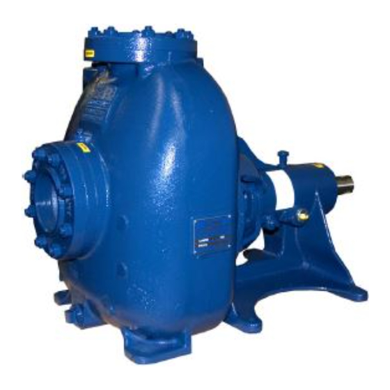
See Figure 1 for the approximate physical dimen some of the information such as mounting, line sions of this pump. OUTLINE DRAWING Figure 1. Pump Model 84A2-B PREINSTALLATION INSPECTION b. Check for and tighten loose attaching hard ware. Since gaskets tend to shrink after dry... -
Page 9: Positioning Pump
OM-00895 80 SERIES Lifting Pump unit weights will vary depending on the mounting and drive provided. Check the shipping tag on the unit packaging for the actual weight, and Only operate this pump in the direction in use lifting equipment with appropriate capacity. dicated by the arrow on the pump body Drain the pump and remove all customer‐installed and on the accompanying decal. -
Page 10: Connections To Pump
80 SERIES OM-00895 mum use of elbows and fittings, which substan Strainers tially increase friction loss. If elbows are necessary, If a strainer is furnished with the pump, be certain use the long‐radius type to minimize friction loss. to use it; any spherical solids which pass through a strainer furnished with the pump will also pass Connections to Pump through the pump itself. -
Page 11: Suction Line Positioning
OM-00895 80 SERIES tance equal to at least 3 times the diameter of the NOTE suction pipe. The pipe submergence required may be reduced by installing a standard pipe increaser fitting at the Suction Line Positioning end of the suction line. The larger opening size will reduce the inlet velocity. -
Page 12: Alignment
80 SERIES OM-00895 air from the top of the pump during the priming Coupled Drives process. This may be accomplished by installing a When using couplings, the axis of the power bypass line from the top of the pump, back to the source must be aligned to the axis of the pump source of liquid. -
Page 13: V-Belt Drives
OM-00895 80 SERIES straightedge to measure the amount of misalign V‐BELT TENSIONING ment. General Rules of Tensioning V‐Belt Drives For new v‐belts, check the tension after 5, 20 and 50 hours of operation and re‐tension as required (see the following procedure for measuring belt When using V‐belt drives, the power source and tension). - Page 14 80 SERIES OM-00895 the smallest sheave diameter is 8 inches, the pump Place the tension tester squarely on the belt at the speed is 1250 RPM, and the belts are uncogged center of the belt span. Apply force on the plunger, Yy‐T type, then 11.5 lbs.
- Page 15 OM-00895 80 SERIES Table 1. Sheave Diameter (Inches) Table 2. Sheave Diameter (Millimeters) Deflection Force (Lbs.) Deflection Force (KG.) Belt Deflection Force Belt Deflection Force Uncogged Cogged Uncogged Cogged Hy‐T Belts & Torque‐Flex Hy‐T Belts & Torque‐Flex Uncogged & Machined Uncogged &...
-
Page 16: Operation - Section C
OM-00895 80 SERIES OPERATION - SECTION C Review all SAFETY information in Section A. Add liquid to the pump casing when: 1. The pump is being put into service for the Follow the instructions on all tags, labels and first time. decals attached to the pump. -
Page 17: Operation
OM-00895 80 SERIES sprinkler heads, and any other fixtures connected from the shaft and seriously damage the to the line. When the discharge line is completely pump. filled, adjust the throttling valve to the required flow Consult the operating manual furnished with the rate. -
Page 18: Pump Vacuum Check
OM-00895 80 SERIES equipment. If backflushing is absolutely neces Cold Weather Preservation sary, liquid pressure must be limited to 50% of the In below freezing conditions, drain the pump to maximum permissible operating pressure shown prevent damage from freezing. Also, clean out any on the pump performance curve (see Section E, solids by flushing with a hose. -
Page 19: Troubleshooting - Section D
80 SERIES OM-00895 TROUBLESHOOTING - SECTION D Review all SAFETY information in Section A. Before attempting to open or service the pump: 1. Familiarize yourself with this man ual. 2. Lock out or disconnect the power source to ensure that the pump will remain inoperative. - Page 20 OM-00895 80 SERIES TROUBLE POSSIBLE CAUSE PROBABLE REMEDY Impeller or other wearing parts worn Replace worn or damaged parts. PUMP STOPS OR FAILS TO DELIVER or damaged. Check that impeller is properly RATED FLOW OR centered and rotates freely. PRESSURE (cont.) Impeller clogged.
-
Page 21: Preventive Maintenance
80 SERIES OM-00895 equipped) between regularly scheduled inspec PREVENTIVE MAINTENANCE tions can indicate problems that can be corrected Since pump applications are seldom identical, and before system damage or catastrophic failure oc pump wear is directly affected by such things as curs. - Page 22 PUMP MAINTENANCE AND REPAIR - SECTION E MAINTENANCE AND REPAIR OF THE WEARING PARTS OF THE PUMP WILL MAINTAIN PEAK OPERATING PERFORMANCE. STANDARD PERFORMANCE FOR PUMP MODEL 84A2-B Based on 70_ F (21_ C) clear water at sea level Contact the Gorman‐Rupp Company to verify per...
- Page 23 80 SERIES OM-00895 SECTION DRAWING PARTS PAGE Figure 1. Pump Model 84A2-B PAGE E - 2 MAINTENANCE & REPAIR...
- Page 24 OM-00895 80 SERIES PARTS LIST Pump Model 84A2‐B (From S/N 818301 Up) If your pump serial number is followed by an “N”, your pump is NOT a standard production model. Contact the Gorman‐Rupp Company to verify part numbers. ITEM PART NAME PART ITEM PART NAME...
- Page 25 80 SERIES OM-00895 PUMP AND SEAL DISASSEMBLY AND REASSEMBLY Review all SAFETY information in Section A. Before attempting to open or service the Follow the instructions on all tags, label and de pump: cals attached to the pump. 1. Familiarize yourself with this man This pump requires little service due to its rugged, ual.
- Page 26 OM-00895 80 SERIES Impeller Removal Before removing the impeller, screw the cross arm on the automatic lubricating grease cup (11) clock Use Only Genuine Gorman-Rupp re wise until it rests against the cover (see Figure 4) to placement parts. Failure to do so may cre prevent the grease in the cup from escaping.
- Page 27 80 SERIES OM-00895 tag the shims, or measure and record their thick retainer from the pedestal bore using a pair of ness for ease of reassembly. screwdrivers against the heads of the machine screws. After removing the bearing retainer, tight en the machine screws.
- Page 28 OM-00895 80 SERIES oughly filtered. NOTE Bearings must be kept free of all dirt and Install the inboard bearing (18) with the integral re foreign material. Failure to do so will great taining ring on the O.D. toward the impeller end of ly shorten bearing life.
- Page 29 80 SERIES OM-00895 Position the oil seal (35) in the bearing cap (34) with the lip positioned as shown in Figure 1. Press the oil seal into the bearing cap until fully seated. Most cleaning solvents are toxic and Install a new O‐ring (17) in the groove in the bear flammable.
- Page 30 OM-00895 80 SERIES SEAL LINER SEAL PLATE SPRING ROTATING ELEMENT IMPELLER STATIONARY WASHERS IMPELLER SHAFT IMPELLER SPACER SHIMS SLEEVE SPACER WASHER ROTATING ELEMENT STATIONARY STATIONARY SEAT SEAT PACKING RINGS Figure 3. Seal Assembly Before installing the seal, lubricate the seal liner with water or a very small amount of oil, and apply a drop of light lubricating oil on the finished faces.
- Page 31 80 SERIES OM-00895 Subassemble the outboard stationary seat, pack pump casing to the seal plate and pedestal with ing ring and stationary washer. Press this unit into the nuts (38). the lubricated seal liner. Install the outboard rotat ing element with the chamfered side toward the impeller.
- Page 32 OM-00895 80 SERIES LUBRICATION capes from the relief hole. Turn the grease cup arm counterclockwise until it is at the top of the stem; this will release the spring to apply grease to the Seal Assembly seal (see Figure 4). Fill the grease cup (11) through the grease fitting with No.
- Page 33 For Warranty Information, Please Visit www.grpumps.com/warranty or call: U.S.: 419-755-1280 Canada: 519-631-2870 International: +1-419-755-1352 GORMAN‐RUPP PUMPS...
Need help?
Do you have a question about the 84A2-B and is the answer not in the manual?
Questions and answers