Table of Contents
Advertisement
Quick Links
OM-00892-03
ABCDE
November 18, 2005
INSTALLATION, OPERATION,
AND MAINTENANCE MANUAL
WITH PARTS LIST
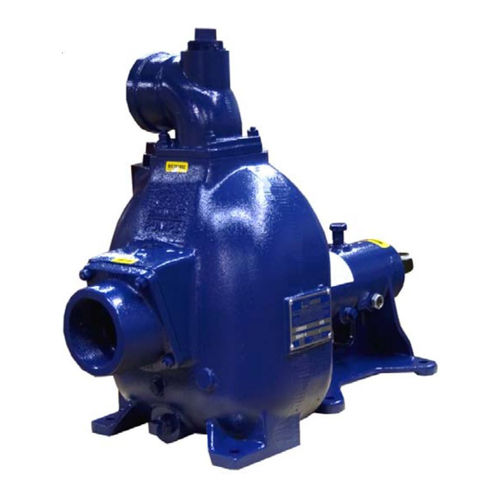
80 SERIES PUMP
MODEL
83B52−B
THE GORMAN-RUPP COMPANY D MANSFIELD, OHIO
www.gormanrupp.com
D
GORMAN-RUPP OF CANADA LIMITED
ST. THOMAS, ONTARIO, CANADA
Printed in U.S.A.
e
Copyright by the Gorman-Rupp Company
Advertisement
Table of Contents

Related Manuals for GORMAN-RUPP PUMPS 83B52-B


Summary of Contents for GORMAN-RUPP PUMPS 83B52-B
- Page 1 OM-00892-03 ABCDE November 18, 2005 INSTALLATION, OPERATION, AND MAINTENANCE MANUAL WITH PARTS LIST 80 SERIES PUMP MODEL 83B52−B THE GORMAN-RUPP COMPANY D MANSFIELD, OHIO www.gormanrupp.com GORMAN-RUPP OF CANADA LIMITED ST. THOMAS, ONTARIO, CANADA Printed in U.S.A. Copyright by the Gorman-Rupp Company...
-
Page 2: Table Of Contents
TABLE OF CONTENTS INTRODUCTION ..........PAGE I −... - Page 3 TABLE OF CONTENTS (continued) TROUBLESHOOTING − SECTION D ......PAGE D − 1 PREVENTIVE MAINTENANCE .
-
Page 4: Introduction
80 SERIES OM−00892 INTRODUCTION Thank You for purchasing a Gorman-Rupp pump. The following are used to alert maintenance per- Read this manual carefully to learn how to safely sonnel to procedures which require special atten- install and operate your pump. Failure to do so tion, to those which could damage equipment, and could result in personal injury or damage to the to those which could be dangerous to personnel:... -
Page 5: Safety - Section A
80 SERIES OM−00892 SAFETY - SECTION A This information applies to 80 Series ba- 6. Vent the pump slowly and cau- sic pumps. Gorman-Rupp has no con- tiously. trol over or particular knowledge of the 7. Drain the pump. power source which will be used. Refer to the manual accompanying the power source before attempting to begin oper- ation. - Page 6 OM−00892 80 SERIES unit and the National Electric Code or closed discharge valve for long periods the applicable local code, the National of time. If operated against a closed dis- or local code shall take precedence. charge valve, pump components will deteriorate, and the liquid could come to a boil, build pressure, and cause the pump casing to rupture or explode.
-
Page 7: Installation − Section Bpage B
80 SERIES OM−00892 INSTALLATION − SECTION B Review all SAFETY information in Section A. specific application. Since the pressure supplied to the pump is critical to performance and safety, Since pump installations are seldom identical, this be sure to limit the incoming pressure to 50% of the section offers only general recommendations and maximum permissible operating pressure as practices required to inspect, position, and ar-... -
Page 8: Preinstallation Inspection
OM−00892 80 SERIES PREINSTALLATION INSPECTION POSITIONING PUMP Pump unit weights will vary depending on the mounting and drive provided. Check the shipping tag on the unit packaging for the actual weight, and Use lifting and moving equipment in use lifting equipment with appropriate capacity. good repair and with adequate capacity Drain the pump and remove all customer-installed to prevent injuries to personnel or dam-... -
Page 9: Materials
80 SERIES OM−00892 Materials line must always slope upward to the pump from the source of the liquid being pumped; if the line Either pipe or hose maybe used for suction and slopes down to the pump at any point along the discharge lines;... -
Page 10: Suction Line Positioning
OM−00892 80 SERIES If there is a liquid flow from an open pipe into the tance equal to at least 3 times the diameter of the sump, the flow should be kept away from the suc- suction pipe. tion inlet because the inflow will carry air down into Suction Line Positioning the sump, and air entering the suction line will re- duce pump efficiency. -
Page 11: Bypass Lines
80 SERIES OM−00892 With high discharge heads, it is recommended that a throttling valve and a system check valve be in- stalled in the discharge line to protect the pump from excessive shock pressure and reverse rota- É tion when it is stopped. É... -
Page 12: Air Release Valve Installation
OM−00892 80 SERIES pressure is dependent upon the discharge head of Air Release Valve Installation the pump at full capacity. The range of the valve The Automatic Air Release Valve must be inde- closing pressure is established by the tension rate pendently mounted in a horizontal position and of the spring as ordered from the factory. -
Page 13: Coupled Drives
80 SERIES OM−00892 either a flexible coupling or V-belt driven system, are the same distance apart at all points (see Fig- the driver and pump must be mounted so that their ure 6A). shafts are aligned with and parallel to each other. It is imperative that alignment be checked after the pump and piping are installed, and before opera- tion. -
Page 14: Drive Belt Tensioning
OM−00892 80 SERIES DRIVE BELT TENSIONING General Rules of Tensioning For new drive belts, check the tension after 5, 20 and 50 hours of operation and re-tension as re- quired (see the following procedure for measuring belt tension). Thereafter, check and re-tension if re- quired monthly or at 500 hour intervals, whichever comes first. -
Page 15: Operation − Section C
OM−00892 80 SERIES OPERATION − SECTION C Review all SAFETY information in Section A. PRIMING Follow the instructions on all tags, labels and Install the pump and piping as described in IN- decals attached to the pump. STALLATION. Make sure that the piping connec- tions are tight, and that the pump is securely mounted. -
Page 16: Starting
OM−00892 80 SERIES STARTING OPERATION Lines With a Bypass Consult the operations manual furnished with the power source. Close the discharge throttling valve (if so equipped) so that the pump will not have to prime If the pump has been approved for use with petro- against the weight of the liquid in the discharge line. -
Page 17: Strainer Check
OM−00892 80 SERIES boil, build pressure, and cause the pump to rup- lift, and should then stabilize. If the vacuum reading ture or explode. If overheating occurs, stop the falls off rapidly after stabilization, an air leak exists. pump and allow it to completely cool before servic- Before checking for the source of the leak, check the point of installation of the vacuum gauge. - Page 18 OM−00892 80 SERIES curately by placing a contact-type thermometer rect level (see LUBRICATION in Section E). Bear- against the housing. Record this temperature for ing overheating can also be caused by shaft future reference. misalignment and/or excessive vibration. A sudden increase in bearing temperatures is a When pumps are first started, the bearings may warning that the bearings are at the point of failing seem to run at temperatures above normal.
- Page 19 80 SERIES OM−00892 TROUBLESHOOTING − SECTION D Review all SAFETY information in Section A. Before attempting to open or service the pump: 1. Familiarize yourself with this man- ual. 2. Lock out or disconnect the power source to ensure that the pump will remain inoperative.
- Page 20 OM−00892 80 SERIES TROUBLE POSSIBLE CAUSE PROBABLE REMEDY Impeller or other wearing parts worn Replace worn or damaged parts. PUMP STOPS OR FAILS TO DELIVER or damaged. Check that impeller is properly RATED FLOW OR centered and rotates freely. PRESSURE (cont.) Impeller clogged.
- Page 21 80 SERIES OM−00892 equipped) between regularly scheduled inspec- PREVENTIVE MAINTENANCE tions can indicate problems that can be corrected Since pump applications are seldom identical, and before system damage or catastrophic failure oc- pump wear is directly affected by such things as curs.
- Page 22 OM−00892 80 SERIES PUMP MAINTENANCE AND REPAIR − SECTION E MAINTENANCE AND REPAIR OF THE WEARING PARTS OF THE PUMP WILL MAINTAIN PEAK OPERATING PERFORMANCE. STANDARD PERFORMANCE FOR PUMP MODEL 83B52−B Based on 70_ F (21_ C) clear water at sea level Contact the Gorman-Rupp Company to verify per- formance or part numbers.
- Page 23 OM−00892 80 SERIES SECTION DRAWING PARTS PAGE Figure 1. Pump Model 83B52−B PAGE E − 2 MAINTENANCE & REPAIR...
- Page 24 OM−00892 80 SERIES PARTS LIST Pump Model 83B52−B (From S/N 1329030 up) If your pump serial number is followed by an N", your pump is NOT a standard production model. Contact the Gorman-Rupp Company to verify part numbers. ITEM PART NAME PART MAT’L ITEM...
- Page 25 OM−00892 80 SERIES PUMP AND SEAL DISASSEMBLY 5. Close the suction and discharge valves. AND REASSEMBLY 6. Vent the pump slowly and cau- Review all SAFETY information in Section A. tiously. 7. Drain the pump. Follow the instructions on all tags, label and de- cals attached to the pump.
- Page 26 80 SERIES OM−00892 charge piping. Remove the hardware securing the the lathe dog and wood block and unscrew the im- pump casing (1) to the base. peller from the shaft. Remove the nuts (33) securing the pump casing Turn and gasket set (35) to the pedestal (18) and seal Counterclockwise plate (34).
- Page 27 OM−00892 80 SERIES Shaft And Bearing Removal And Disassembly When the pump is properly operated and main- tained, the pedestal should not require disassem- To prevent damage during removal from bly. Disassemble the shaft and bearings only the shaft, it is recommended that bearings when there is evidence of wear or damage.
- Page 28 80 SERIES OM−00892 Replace the bearings, shaft, or pedestal if the curred, use a suitably sized sleeve and a press to proper bearing fit is not achieved. reposition the bearings. If heating the bearings is not practical, use a suit- If bearing replacement is required, use a bearing ably sized sleeve and an arbor (or hydraulic) press puller to remove the inboard and outboard bear-...
- Page 29 OM−00892 80 SERIES Seal Reassembly and Installation finished faces; even fingerprints on the faces can shorten seal life. If necessary, clean the faces with a (Figures 1 and 3) non-oil based solvent and a clean, lint-free tissue. Wipe lightly in a concentric pattern to avoid Clean the seal cavity and shaft with a cloth soaked scratching the faces.
- Page 30 80 SERIES OM−00892 After the back clearance is set, secure the impeller with the hardware (37, 38 and 39). Pump Casing Installation This seal is not designed for operation at If the wear plate assembly (36) was removed, posi- temperatures above 160_F (71_C). Do not tion the replacement wear plate assembly squarely use at higher operating temperatures.
- Page 31 OM−00892 80 SERIES side of the pump casing. Install the suction flange Bearings (52) and secure with the nuts (54). Check the oper- The pedestal was fully lubricated when shipped ation of the check valve to ensure proper seating from the factory. Check the oil level regularly and free movement.
- Page 32 For U.S. and International Warranty Information, Please Visit www.grpumps.com/warranty or call: U.S.: 419−755−1280 International: +1−419−755−1352 For Canadian Warranty Information, Please Visit www.grcanada.com/warranty or call: 519−631−2870 THE GORMAN-RUPP COMPANY D MANSFIELD, OHIO GORMAN-RUPP OF CANADA LIMITED ST. THOMAS, ONTARIO, CANADA...
Need help?
Do you have a question about the 83B52-B and is the answer not in the manual?
Questions and answers