GORMAN-RUPP PUMPS 80 Series Installation, Operation, And Maintenance Manual With Parts List
Hide thumbs
Also See for 80 Series:

Related Manuals for GORMAN-RUPP PUMPS 80 Series


Summary of Contents for GORMAN-RUPP PUMPS 80 Series
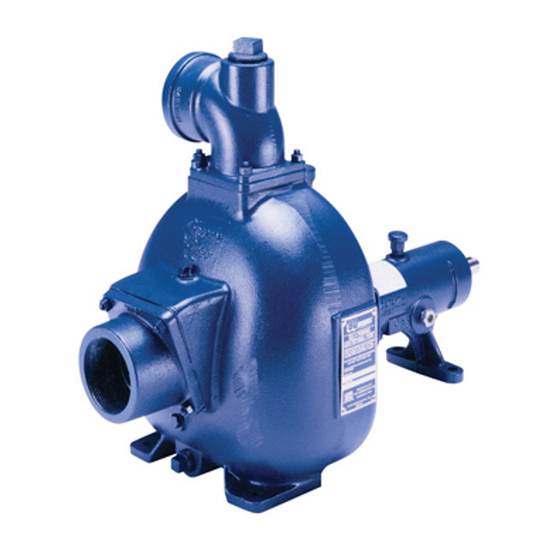
- Page 1 OM-06753-01 March 20, 2015 INSTALLATION, OPERATION, AND MAINTENANCE MANUAL WITH PARTS LIST 80 SERIES PUMP MODEL 86A2-QSF2.8P FT4 GORMAN‐RUPP PUMPS www.grpumps.com 2015 Gorman‐Rupp Pumps Printed in U.S.A.
- Page 2 Register your new Gorman‐Rupp pump online at www.grpumps.com Valid serial number and e‐mail address required. The engine exhaust from this product contains chemicals known to the State of California to cause cancer, birth defects or other reproductive harm. RECORD YOUR PUMP MODEL AND SERIAL NUMBER Please record your pump model and serial number in the spaces provided below.
-
Page 3: Table Of Contents
TABLE OF CONTENTS INTRODUCTION ..........PAGE I - 1 SAFETY ‐... - Page 4 TABLE OF CONTENTS (continued) PUMP MAINTENANCE AND REPAIR ‐ SECTION E ....PAGE E - 1 STANDARD PERFORMANCE CURVE ........PAGE E - 1 PARTS LISTS: Pump Model...
-
Page 5: Introduction
80 SERIES OM-06753 INTRODUCTION Thank You for purchasing a Gorman‐Rupp pump. HAZARD AND INSTRUCTION Read this manual carefully to learn how to safely DEFINITIONS install and operate your pump. Failure to do so could result in personal injury or damage to the The following are used to alert maintenance per... -
Page 6: Safety - Section A
80 SERIES OM-06753 SAFETY - SECTION A This information applies to 80 Series en danger personnel as a result of pump failure. gine driven pumps. Refer to the manual accompanying the engine before at tempting to begin operation. Because pump installations are seldom... - Page 7 OM-06753 80 SERIES heated pump. Vapor pressure within the pump can cause parts being disen gaged to be ejected with great force. Al low the pump to completely cool before Allow an over‐heated pump to com servicing. pletely cool before servicing. Do not re...
-
Page 8: Installation - Section B
80 SERIES OM-06753 INSTALLATION - SECTION B Review all SAFETY information in Section A. specific application. Since the pressure supplied to the pump is critical to performance and safety, Since pump installations are seldom identical, this be sure to limit the incoming pressure to 50% of the section offers only general recommendations and maximum permissible operating pressure. -
Page 9: Preinstallation Inspection
OM-06753 80 SERIES Table 1. Battery Specifications PREINSTALLATION INSPECTION Cold Reserve Approx. Crank Capacity Amp/ Overall Amps @80°F Dims. Voltage @ 0°F (Minutes) Rating (Inches) The pump assembly was inspected and tested be 20.5L fore shipment from the factory. Before installation, inspect the pump for damage which may have oc... -
Page 10: Mounting
80 SERIES OM-06753 Mounting Lines near the pump must be independently sup ported to avoid strain on the pump which could cause excessive vibration, decreased bearing life, Locate the pump in an accessible place as close as and increased shaft and seal wear. If hose‐type practical to the liquid being pumped. -
Page 11: Sealing
OM-06753 80 SERIES of solids larger than the solids handling capability Suction Line Positioning of the pump. The depth of submergence of the suction line is This pump is designed to handle up to 1‐15/16 inch critical to efficient pump operation. Figure 2 shows (49,21 mm) diameter spherical solids. -
Page 12: Bypass Lines
80 SERIES OM-06753 from excessive shock pressure and reverse rota air from the top of the pump during the priming tion when it is stopped. process. This may be accomplished by installing a bypass line from the top of the pump, back to the source of liquid. -
Page 13: Operation - Section C
OM-06753 80 SERIES OPERATION - SECTION C OPERATION Review all SAFETY information in Section A. Make sure the pump is level. Lower jack Follow the instructions on all tags, labels and stands and chock the wheels, if so decals attached to the pump. -
Page 14: Lines With A Bypass
OM-06753 80 SERIES Add liquid to the pump casing when: continuous operating speed for this pump. 1. The pump is being put into service for the first time. A Gorman‐Rupp automatic air release valve may 2. The pump has not been used for a consider... -
Page 15: Leakage
OM-06753 80 SERIES Liquid Temperature And Overheating The maximum liquid temperature for this pump is F (71 C). Do not apply it at a higher operating Do not operate the pump against a temperature. closed discharge throttling valve for Overheating can occur if operated with the valves long periods of time. -
Page 16: Stopping
OM-06753 80 SERIES shock waves can be transmitted to the pump and into service. Consult the factory for ad piping system. Close all connecting valves slowly. ditional information. PERIODIC CHECKS Stopping Seal Cavity and Bearing Lubrication Reduce the throttle speed slowly, and allow the en... -
Page 17: Cold Weather Preservation
OM-06753 80 SERIES Consult the manual accompanying the engine, for approximately one minute; this will remove any and change the oil filter periodically as indicated. If remaining liquid that could freeze the pump rotat operated under extremely dusty conditions, ing parts. If the pump will be idle for more than a change the filter more frequently. -
Page 18: Troubleshooting - Section D
80 SERIES OM-06573 TROUBLESHOOTING - SECTION D Review all SAFETY information in Section A. Before attempting to open or service the pump: 1. Familiarize yourself with this man ual. 2. Switch off engine ignition and dis connect the positive battery cable to ensure that the pump will re... - Page 19 OM-06573 80 SERIES TROUBLE POSSIBLE CAUSE PROBABLE REMEDY PUMP STOPS OR FAILS Suction intake not submerged at Check installation and correct sub proper level or sump too small. mergence as needed. TO DELIVER RATED FLOW OR PRESSURE Impeller or other wearing parts worn Replace worn or damaged parts.
-
Page 20: Preventive Maintenance
80 SERIES OM-06573 equipped) between regularly scheduled inspec PREVENTIVE MAINTENANCE tions can indicate problems that can be corrected Since pump applications are seldom identical, and before system damage or catastrophic failure oc pump wear is directly affected by such things as curs. - Page 21 80 SERIES OM-06753 PUMP MAINTENANCE AND REPAIR ‐ SECTION E MAINTENANCE AND REPAIR OF THE WEARING PARTS OF THE PUMP WILL MAINTAIN PEAK OPERATING PERFORMANCE. STANDARD PERFORMANCE FOR PUMP MODEL 86A2-QSF2.8P FT4 Based on 70 F (21 C) clear water at sea level Contact the Gorman‐Rupp Company to verify per...
- Page 22 OM-06753 80 SERIES ILLUSTRATION PARTS PAGE Figure 1. Pump Model 86A2-QSF2.8P FT4 PAGE E - 2 MAINTENANCE & REPAIR...
- Page 23 80 SERIES OM-06753 PARTS LIST Pump Model 86A2-QSF2.8P FT4 (From S/N 1583673 Up) If your pump serial number is followed by an “N”, your pump is NOT a standard production model. Contact the Gorman‐Rupp Company to verify part numbers. ITEM...
- Page 24 OM-06753 80 SERIES ILLUSTRATION Figure E-2. 46143-181 Power Unit Kit PAGE E - 4 MAINTENANCE & REPAIR...
- Page 25 80 SERIES OM-06753 PARTS LIST 46143-181 Power Unit Kit ITEM PART NAME PART ITEM PART NAME PART NUMBER NUMBER BASE/FUEL TANK ASSY 41553-029 24150 HOSE BARB FITTING 26523-447 QSF2.8P FT4 ENGINE 29216-401 AIR VENT S1703 CONT PANEL INST KIT 48122-553...
- Page 26 OM-06753 80 SERIES ILLUSTRATION Figure 3. 86A2-(SAE 4/10) Pump End Assembly PAGE E - 6 MAINTENANCE & REPAIR...
- Page 27 80 SERIES OM-06753 PARTS LIST 86A2-(SAE 4/10) Pump End Assembly ITEM PART NAME PART ITEM PART NAME PART NUMBER NUMBER PUMP CASING SEE NOTE BELOW IMPELLER SHAFT 45 15010 INTERMEDIATE 36 10010 IMPELLER 2521B 10010 INTERMEDIATE GUARD 42381-031 24152 GREASE SEAL ASSY.
- Page 28 OM-06753 80 SERIES ILLUSTRATION Figure 4. 86A2-(SAE 4/10) Drive Assembly PARTS LIST ITEM PART PART NAME NUMBER COUPLING KIT 48112-001 -BUSHING 24131-345 -COUPLING ASSEMBLY 44165-011 SOCKET HD CAPSCREW BD0606-1/2 15991 SOCKET HD CAPSCREW 22644-220 LOCKWASHER J06 15991 LOCKWASHER 21171-536 HEX HD CAPSCREW...
- Page 29 80 SERIES OM-06753 PUMP AND SEAL DISASSEMBLY 3. Allow the pump to completely cool if overheated. AND REASSEMBLY 4. Check the temperature before opening any covers, plates, or Review all SAFETY information in Section A. plugs. 5. Close the suction and discharge Follow the instructions on all tags, label and de...
- Page 30 OM-06753 80 SERIES Separating Pump and Intermediate from Reach through the suction port and wedge a block Engine of wood between the vanes of the impeller and the pump casing to prevent rotation. (Figure 4) If removed, install the shaft key (30) in the shaft If the impeller or seal assembly require replace...
- Page 31 80 SERIES OM-06753 place the gasket set as required. For ease of reas Inspect the seal liner (44) for wear or grooves that sembly, tie and tag the gaskets or measure and re could cause leakage or damage to the seal pack...
- Page 32 OM-06753 80 SERIES If bearing replacement is required, use a bearing puller to remove the inboard and outboard bearing cones (28) from the shaft. To prevent damage during removal from Shaft and Bearing Reassembly and Installation the shaft, it is recommended that bearings be cleaned and inspected in place.
- Page 33 80 SERIES OM-06753 If heating the bearings is not practical, use a suit Seal Reassembly and Installation ably sized sleeve and an arbor (or hydraulic) press (Figures 3 and 6) to install the bearing cones on the shaft. Clean the seal cavity and shaft with a cloth soaked in fresh cleaning solvent.
- Page 34 OM-06753 80 SERIES GREASE CUP SEAL PIPING PLATE PACKING RINGS SEAL IMPELLER LINER STATIONARY SEAL SEAL SEATS WASHER IMPELLER SHAFT ROTATING ELEMENTS IMPELLER SHIMS SPRING SPACER SLEEVE STATIONARY WASHERS Figure 6. Seal Assembly Slide the seal plate over the shaft until fully seated against the intermediate.
- Page 35 80 SERIES OM-06753 Slide the seal spacer washer (21) onto the shaft Securing Intermediate and Drive Assembly To with the chamfered side facing the shaft shoulder. Engine (Figure 4) Reinstall the automatic grease cup and piping (17, 18 and 19) in the seal plate. After the impeller has Install the shaft key (30, Figure 3) in the shaft key...
- Page 36 OM-06753 80 SERIES Using a suitable lifting device, position the interme bly (1) to the base with the previously removed diate so the flexible portion of the coupling seats in hardware. side the outer ring attached to the engine flywheel.
- Page 37 80 SERIES OM-06753 capes from the relief hole. Turn the grease cup arm LUBRICATION counterclockwise until it is at the top of the stem; Seal Assembly this will release the spring to apply grease to the (Figure 3) seal (see Figure 7).
- Page 38 For U.S. and International Warranty Information, Please Visit www.grpumps.com/warranty or call: U.S.: 419-755-1280 International: +1-419-755-1352 For Canadian Warranty Information, Please Visit www.grcanada.com/warranty or call: 519-631-2870 GORMAN‐RUPP PUMPS...
Need help?
Do you have a question about the 80 Series and is the answer not in the manual?
Questions and answers