Table of Contents
Advertisement
Quick Links
Advertisement
Table of Contents

Related Manuals for Powermat PM-IMG-210S


Summary of Contents for Powermat PM-IMG-210S
- Page 1 USER MANUAL inverter welder PM-IMG-210S ORIGINAL INSTRUCTIONS...
-
Page 2: Table Of Contents
Table of Contents SYMBOLS WARNING / INFORMATION ..................2 APPLICATION EQUIPMENT ......................... 2 TECHNICAL DATA ..........................2 SAFETY ........................... 3 GENERAL THOUGHTS ............................3 Safety during welding ....................3 ..Electromagnetic field .......... -
Page 3: Symbols Warning / Information
For resulting from improper use damage or injuries responsibility of the user / operator and not the manufacturer. Producer in order to improve its products reserves the right to possibility of differences in the above mentioned product. TECHNICAL DATA Model: PM-IMG-210S Welding method MIG / MAG Power 230V / 50Hz... -
Page 4: Safety
SECURITY Before starting work carefully to become familiar with the manual. Keep them for future reference. For damages resulting from failure to observe these instructions, the manufacturer is not liable. The greatest danger is prohibited to perform the following steps: and) Welders use for purposes other than those described in the manual. - Page 5 Electromagnetic may interfere with pacemakers. Welding cables should be arranged in parallel, as close as possible to each other. SPARKS CAN CAUSE FIRE: Sparks generated during welding can cause fire, explosion and burns SPARKS CAN CAUSE FIRE: Sparks generated during welding can cause fire, explosion and burns unprotected skin.
-
Page 6: Electromagnetic Field
STATIC DISCHARGE MAY DAMAGE THE PRINTED CIRCUIT: Before touching the printed circuit STATIC DISCHARGE MAY DAMAGE THE PRINTED CIRCUIT: Before touching the printed circuit boards and parts of the electrical system should be assumed grounding wrist-strap. Use of antistatic packaging is storing and transporting electrical components. READ INSTRUCTIONS: Carefully read the manual and follow the information contained therein. -
Page 7: Description Of The Device
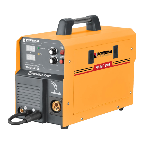
DESCRIPTION OF THE DEVICE Model: PM-IMG-210S 1. Power LED Wire feed speed knob 2. LED overload Welding current control at the MMA 3. ammeter The switch MIG / MMA 4. voltmeter Presses the wire feed speed 5. The socket welding torch MMA 10. -
Page 8: Description Of Symbols On The Label
ABOUT MARKING THE PIS LABEL ABOUT MARKING THE PIS LABEL ABOUT MARKING THE PIS LABEL Current (DC) single phase alternating current (AC) of the rated frequency 50Hz Symbol and 60Hz operating frequency. Nominal input voltage (AC) Nominal input voltage (AC) Nominal input voltage (AC) Maximum input current Maximum input current... -
Page 9: Current Power And Grounding
Current power and grounding. Only qualified personnel may perform installation and modification of the electricity grid. Attention! It is forbidden to use the device or completely dismantled the housing removed, it may cause electric shock Attention! It is forbidden to use the device or completely dismantled the housing removed, it may cause electric shock and lead to severe injury. - Page 10 Fig. 1 connection device Attaching the welding wire 1. Before the spool of wire, make sure that the roller drive unit 1. Before the spool of wire, make sure that the roller drive unit correspond to the type and diameter of the welding wire fed. Rollers with a groove of V-shaped correspond drutom steel, while the U-shaped drutom aluminum.
-
Page 11: Mag Welding
2. Remove the protective cap and unscrew the cylinder valve briefly to remove 2. Remove the protective cap and unscrew the cylinder valve briefly to remove possible contaminants. 3. Install the regulator so that the gauge was in a vertical position. 3. - Page 12 through the gas nozzle is located on the torch. Gas protects the molten metal from the atmosphere, pollution and cooled welding torch. Fig. 2 Scheme MIG / MAG Fig. 2 Scheme MIG / MAG Material should be completely cleaned of contaminants such as rust or paint. Any dirt have an impact on changing the direction of welding and weld weakness.
- Page 13 It is possible to weld with poor fitting the amperage, penetration may be too large or too small, but the welds remain valid. By contrast, the mismatched wire feed speed, welding can not be obtained. The method for selecting a wire feed speed experimentation.
-
Page 14: Welding Method Fcaw (Flux Cored) - Only For Devices With Alternating Polarity. 13 Mma Welding
Welding method FCAW (Flux Cored) - only for devices with alternating polarity. Attention! When welding wire shielding itself must change the polarity of the device. 1. Make sure that the welding machine is disconnected from the power source. 1. Make sure that the welding machine is disconnected from the power source. 2. -
Page 15: Basic Information For Welding Mma
Figure 3 Figure 3. One specific example of welding by means of electrodes. Figure 3. One specific example of welding by means of electrodes. Attention! At the time of exceeding the cycle provided for the amperage thermal circuit breaker lock the device Attention! At the time of exceeding the cycle provided for the amperage thermal circuit breaker lock the device (indicated by yellow LED Overload) until cool welding. -
Page 16: Welding Electrodes In Practice
It is recommended that during welding work in the horizontal and vertical positions. However, while we are forced to weld in vertical or overhead should set the current lower than the level during operation. The best welds are obtained while maintaining a short arc, smooth movement of the electrode and the electrode leading down at a constant speed during melting. -
Page 17: Electric Arc Welding
Electric arc welding Fig. 4 Figure 4. Presents phenomena occurring during arc welding, which is greatly enlarged what is seen by the welder. Figure 4. Presents phenomena occurring during arc welding, which is greatly enlarged what is seen by the welder. Curved space is shown in a central position in the picture. -
Page 18: Correct Welding Position
differences in the types of buffer zones to gain knowledge select the right electrode for the job. When choosing the electrodes need to consider: 1. Implementation example. Steel, mild steel and stainless steel. 1. Implementation example. Steel, mild steel and stainless steel. 2. -
Page 19: Proper Arc Length
Proper arc length Arc length is the distance from the end of the electrode to the workpiece. Once the arc is stabilized setting proper arc length is very important. Arc should have a length of approximately 1.5 - 3mm. Due to the burning of the electrodes must be kept adjust the length of the arc. -
Page 20: Insrukcja Installation And Use
most sheets, plates, pipes, rolling, angles, beams. This type of steel can usually pospawać without special precautions. However, some types of steel contain large amounts of carbon. Such steels are most commonly used in the connecting rods, knives and cutting grinding, axles, shafts, plowshares. Carbon steels in most cases can be welded with success, however, caution should be exercised in maintaining proper temperatures in the earlier welding and reheating the material to be welded. -
Page 21: Service
Thanks re-use, material utilization or other forms of old appliances, you make an important contribution to protecting our environment. COMPANY DETAILS PH Powermat TMK Bijak Sp. General Partnership Ul. Defenders of the Gdansk Post 97 42-400 Zawiercie twenty... -
Page 22: Declaration Of Conformity
DECLARATION OF CONFORMITY...
Need help?
Do you have a question about the PM-IMG-210S and is the answer not in the manual?
Questions and answers