
Related Manuals for Powermat PM-220L-IMGS


Summary of Contents for Powermat PM-220L-IMGS
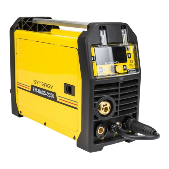
- Page 1 PM0698 USER MANUAL PLACE OF MACHINE IMAGE HERE Inverter Welder PM-220L-IMGS Synergy ORIGINAL INSTRUCTIONS...
-
Page 2: Table Of Contents
TABLE OF CONTENTS TABLE OF CONTENTS ..................................2 SYMBOLS WARNING / INFORMATION ........................4 PURPOSE OF THE DEVICE ............................5 SAFETY ................................6 Safety during welding ..........................6 General safety .......... - Page 3 The correct welding speed ..........................23 Practice welding ..............................23 Practical exercise ..............................23 Base metals ..............................24 DISADVANTAGES OF JOINT ................................... 25 EDGE PREPARATION METHOD In the MIG / MAG ....................27 TECHNOLOGY MIG / MAG ..........
-
Page 4: Symbols Warning / Information
SYMBOLS WARNING / INFORMATION ATTENTION: Before using the device please read the instruction manual and safety instructions. Keep ATTENTION: Before using the device please read the instruction manual and safety instructions. Keep these instructions. ATTENTION: General warning sign notes for each user on the general danger. It is combined with other ATTENTION: General warning sign notes for each user on the general danger. -
Page 5: Purpose Of The Device
PURPOSE OF THE DEVICE The device is used for welding of any type electrodes and the welding wire. The product to which this manual is electronically controlled semi-automatic welding professional synergistic effect with the "single and double pulse". For manual, electric welding of low carbon steel, low alloy, stainless high and low alloy steel, aluminum and its alloys, copper and its alloys, braze, etc. -
Page 6: Safety
SECURITY This section covers basic safety rules when working with the use of semi-automatic welding SECURITY DURING WELDING SECURITY DURING WELDING ELECTRIC SHOCK CAN KILL: Welding apparatus produce a high voltage. Do not touch the torch, welding ELECTRIC SHOCK CAN KILL: Welding apparatus produce a high voltage. Do not touch the torch, welding material connected when the device is turned on to the network. - Page 7 POWER SUPPLY: Disconnect the power supply before carrying out any work, repairs on the device. POWER SUPPLY: Disconnect the power supply before carrying out any work, repairs on the device. Regularly check the welding cables. If you note any damage to the wire or insulation should be removed immediately.
-
Page 8: General Safety
ARC WELDING CAN CAUSE INTERFERENCE: Electromagnetic energy can interfere with ARC WELDING CAN CAUSE INTERFERENCE: Electromagnetic energy can interfere with electronic equipment such as computers and computer-controlled equipment. Make sure that the hardware devices in welding work environment electromagnetically compatible. To minimize the potential for interference stick welding wires close to each other, as close to the ground. -
Page 9: Electromagnetic Field
• Place the wire away from the work area and keep that in mind so that it is for the person that supports the device. • Do not use damaged cables, connectors, plugs, or inconsistent with the provisions of the connecting cables. In case of damage or cut power cord immediately pull the plug from the socket. -
Page 10: Description Of The Device
DESCRIPTION OF THE DEVICE And Front Panel DESCRIPTION OF Socket welding torch MMA (+) Handle Command socket holder with built-in wire feeder and the magazine (SPOOL Cover the control panel GUN) Control panel Slot ground cable (-) button 4. Multi-function knob 4. - Page 11 II Description of the control panel DESCRIPTION OF The choice of method of welding The wire feed The selection of the type of gas to the welding material 6. LCD display The selection of the type of gas to the welding material 6. LCD display The selection of the type of gas to the welding material 6.
-
Page 12: Description Of Symbols On The Label
III Description of the rear of the enclosure DESCRIPTION OF 230V AC power socket Connector to connect the hose to the gas 2. On / off switch 2. On / off switch DESCRIPTION OF SYMBOLS ON THE LABEL Current (DC) Symbol single phase alternating current (AC) of the rated frequency 50Hz and 60Hz operating frequency. -
Page 13: Technical Data
The device welded single-phase DC Welder is used for MMA welding Welder is used for MIG / MAG welding TECHNICAL DATA Model PM-220L-IMGS Welding method MIG / MAG Power 230V / 50Hz recommended 25 [A] security 6.1 kVA 5.8 kVA... -
Page 14: Basic Steps Before You Begin Working
d) circuit of the welding current should not be grounded, except for the cases when the objects welded are connected to ground. e) welding the connecting wires welded to the subject power source to be connected directly to the subject or instrumentation, as close as possible to the welding point. -
Page 15: Final Remarks
b) Check whether the welding position or a position next to the fire was not dusty. c) Organize your work station, remove the tip electrodes and welding slag. d) Organize welding equipment. FINAL BALANCE FINAL BALANCE a) When performing welding work inside the tanks, boilers or other confined spaces (up to 15m a) When performing welding work inside the tanks, boilers or other confined spaces (up to 15m a) When performing welding work inside the tanks, boilers or other confined spaces (up to 15m welder should be insured by another... -
Page 16: Connection Of Protective Gas
9. Switch on the machine, expand the handle so as to be in a straight line, then press the button on the handle until 9. Switch on the machine, expand the handle so as to be in a straight line, then press the button on the handle until until the wire in the outlet (approx. -
Page 17: Welding Wire Holder Magazine (Spool Gun)
HANDLE supplying magazine WIRE (SPOOL GUN) HANDLE supplying magazine WIRE (SPOOL GUN) It should connect the socket holder (7) of the front panel, and then place the plug to the polarity of the socket (+) and the ground cable clamp on the welded material. Then switch to switch within the housing change the wire feeder. -
Page 18: Welding By Tig-Lift
ANEL CONTROL ANEL CONTROL BUTTONS AND DIAL BACKGROUND BUTTONS AND DIAL BACKGROUND Knob parameters. To confirm the selected value, press the center button (N-LIFT TIG mode). Mode select button (welding method): Manual MIG / MAG: It allows you to select the optimal voltage and wire feed speed for ideal Manual MIG / MAG: It allows you to select the optimal voltage and wire feed speed for ideal welding parameters. - Page 19 DISPLAY ALTHOUGH DISPLAY ALTHOUGH CODE DESCRIPTION voltage symbol voltage symbol Current symbol The speed of the wire feed welding current INDUCTANCE -10 ~ + 10 Adjusting the inductance allows for optimization of the arc depending on the thickness of the welded plate and the methods and conditions for welding.
-
Page 20: Basic Information For Welding
The voltage reduction. The task is to turn the power off within a few milliseconds after the end of welding. This function is also responsible for reducing the voltage on the electrode wrapped to a safe level. The "On" The "Off" BASIC INFORMATION FOR WELDING Otulinowymi welding electrodes (MMA) is a process in which metal is melted, and then combined, by heating it by means of electric arc with consumable electrode coated metal wrapper flux. -
Page 21: Electric Arc Welding
The electric arc is formed in a space between the work piece and the welding electrode tip mounted on the torch. The molten metal moves along the arc for the combination of materials, forming a weld bond. Electrode Welding requires a strong grip and a welding tip, stable hands, good vision and good mental health. The operator controls the welding arc welding and thus, the quality of the weld created. -
Page 22: Correct Welding Position
The differences for the different types of electrodes refer mainly to the type of the buffer zone. Changing the outer coating significantly affects the characteristics of welding. By understanding the differences in the types of buffer zones to gain knowledge select the right electrode for the job. -
Page 23: Proper Arc Length
ARC LENGTH RAWIDŁOWA ARC LENGTH RAWIDŁOWA Arc length is the distance from the end of the electrode to the workpiece. Once the arc is stabilized setting proper arc length is very important. Arc should have a length of approximately 1.5 - 3mm. Due to the burning of the electrodes must be kept adjust the length of the arc. -
Page 24: Base Metals
and) Learn how to kindle a bow by rubbing on metal electrodes. Make sure that the angle of the electrode is correct and) Learn how to kindle a bow by rubbing on metal electrodes. Make sure that the angle of the electrode is correct and that you're using both hands. -
Page 25: Disadvantages Of Joint
DISADVANTAGES OF JOINT lack of penetration rise time, if bevel angle is too small, the spacing between the edges of sheet metal (pipes) is too small or the lack of penetration rise time, if bevel angle is too small, the spacing between the edges of sheet metal (pipes) is too small or the threshold is too high. - Page 26 choosing the correct number of layers that must be done in the connector so that the last layer was not an excessive riser. flooding They are present at the border (both sides) of the base metal and the weld face and root of the weld. The occurrence of this defect is flooding They are present at the border (both sides) of the base metal and the weld face and root of the weld.
-
Page 27: Edge Preparation Method In The Mig / Mag
EDGE PREPARATION METHOD In the MIG / MAG... -
Page 28: Technology Mig / Mag
TECHNOLOGY MIG / MAG GMA welding process involves melting the material of the welded metal and the consumable electrode arc heat glowing between the electrode and the welded object, the inert gas or active. The weld metal is formed so the fusing of the electrode material and nadtopionych welded edges of objects. -
Page 29: Practical Advice Mig / Mag
glowing between the consumable electrode and the weld material ensures that the weld is formed in a very favorable thermal conditions and metallurgy. GMA welding can thus be used for implementing the high quality of the connections of all the metals which may be joined by arc welding. -
Page 30: Ways Of Transfer Of Metal Arc
Excessive lengthening or shortening the arc can cause unstable arc glow and poor weld quality. L1, L2 - arc length The depth of penetration is also significantly impact the direction of welding - carrying the torch. H1, H2 - the depth of penetration WAYS OF TRANSFER OF METAL arc Due to the nature of the shielding gas and the electrical parameters of the welding process (voltage and current) There are three ways to change the physical state of the metal in the arc welding:... -
Page 31: Maintenance And Storage
reducing the copper welding with high heat input arc better 25-20% Ar + N 25-20% Ar + N glow than the arc shield 100% N glow than the arc shield 100% N weakly oxidizing recommended primarily for the welding of stainless steels and alloy steels Ar + 12% O Ar + 12% O oxidizing recommended for welding of carbon steels and low alloy steels... -
Page 32: Storage
SERVICE Repair of power tools should only be done by qualified personnel using original spare parts. This ensures the safety of the device. Address: Powermat service ul. Defenders of the Gdansk Post 97 42-400 Zawiercie Tel. 32 670 39 68 4 internal e-mail serwis@powermat.pl... -
Page 33: Removal Of Used
You can also refer to the old appliance collection point. For more information on the collection system equipment is at hand: https://sklep.powermat.pl/webpage/pl/recycling.html COMPANY DETAILS PH Powermat TMK Bijak Sp. General Partnership Ul. Defenders of the Gdansk Post 97 42-400 Zawiercie http://www.powermat.pl CHART PARTS...
Need help?
Do you have a question about the PM-220L-IMGS and is the answer not in the manual?
Questions and answers