Table of Contents
Advertisement
Quick Links
Advertisement
Table of Contents

Related Manuals for Powermat PM-IMG-220G


Summary of Contents for Powermat PM-IMG-220G
- Page 1 USER MANUAL inverter welder PM-IMG-220G ORIGINAL INSTRUCTIONS...
-
Page 2: Table Of Contents
Table of Contents SYMBOLS WARNING / INFORMATION ..................3 APPLICATION EQUIPMENT ......................... 3 TECHNICAL DATA ..........................3 SAFETY ........................... 4 GENERAL THOUGHTS ............................4 Safety during welding ....................4 ..Electromagnetic field .......... - Page 3 Maintenance ............................22 Malfunctions welding ........................ 23 Service ..............................24 REMOVAL OF USED ......................24 COMPANY INFORMATION ..........................24 DECLARATION OF CONFORMITY ........................25...
-
Page 4: Symbols Warning / Information
SYMBOLS WARNING / INFORMATION WARNING: Before using the device please read the instruction manual and safety instructions. WARNING: Before using the device please read the instruction manual and safety instructions. Keep these instructions. WARNING: Keep a safe distance from bystanders during operation. WARNING: Keep a safe distance from bystanders during operation. -
Page 5: Safety
SECURITY Before starting work carefully to become familiar with the manual. Keep them for future reference. For damages resulting from failure to observe these instructions, the manufacturer is not liable. The greatest danger is prohibited to perform the following steps: and) Welders use for purposes other than those described in the manual. - Page 6 Electromagnetic may interfere with pacemakers. Welding cables should be arranged in parallel, as close as possible to each other. SPARKS CAN CAUSE FIRE: Sparks generated during welding can cause fire, explosion and burns SPARKS CAN CAUSE FIRE: Sparks generated during welding can cause fire, explosion and burns unprotected skin.
-
Page 7: Electromagnetic Field
STATIC DISCHARGE MAY DAMAGE THE PRINTED CIRCUIT: Before touching the printed circuit STATIC DISCHARGE MAY DAMAGE THE PRINTED CIRCUIT: Before touching the printed circuit boards and parts of the electrical system should be assumed grounding wrist-strap. Use of antistatic packaging is storing and transporting electrical components. READ INSTRUCTIONS: Carefully read the manual and follow the information contained therein. -
Page 8: Description Of The Device
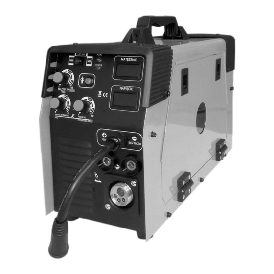
DESCRIPTION OF THE DEVICE PM-MIG-220T Ammeter Wire feed speed knob (MIG) LED overload 9. Voltmeter (MIG) 9. Voltmeter (MIG) 10. Socket polarity (+) 10. Socket polarity (+) The switch MIG / MMA / TIG-LIFT LED planting 11. Socket polarity (-) 11. -
Page 9: Description Of Symbols On The Label
ABOUT MARKING THE PIS LABEL ABOUT MARKING THE PIS LABEL ABOUT MARKING THE PIS LABEL Current (DC) Symbol single phase alternating current (AC) of the rated frequency 50Hz and 60Hz operating frequency. Nominal input voltage (AC) Nominal input voltage (AC) Nominal input voltage (AC) Maximum input current Maximum input current... -
Page 10: Welding Service
Warning! It is forbidden to use the device or completely dismantled the housing removed, it may cause electric shock Warning! It is forbidden to use the device or completely dismantled the housing removed, it may cause electric shock and lead to severe injury. Do not touch the energized equipment. Before installing the unit, check electrical network to which the device is connected meets the requirements placed on the nameplate and that it meets all local and national standards. - Page 11 Fig. 1 of the connection device deterministic (for welding shield Connect a gas cylinder in accordance with the drawing of gas into the socket so the device) Attaching the welding wire 1. Before the spool of wire, make sure that the roller drive unit 1.
-
Page 12: Welding Mma
Connection of protective gas 1. The bottle of carefully selected protective gas must be set on the shelf and semi-automatic 1. The bottle of carefully selected protective gas must be set on the shelf and semi-automatic secured by a chain. 2. -
Page 13: Mig
MIG MIG MIG MIG - welding process, wherein the shielding gas used is chemical inert gas, for example. Argon, helium. - welding process, wherein the shielding gas used is chemical inert gas, for example. Argon, helium. 1. Make sure that the welder is odłączna power. 1. -
Page 14: Mig
During welding, the torch moves the welding wire, which is constantly melting in an electric arc. The fluid material of the welding wire connected to a combination of material to form a liquid weld pool. When moving the welding torch, lake follow, to solidify at the edges and creating a durable combination of materials. - Page 15 lead to burnout material welded. If the weld does not break down this welding dispenses too quickly and the seam is not melted through the material. Increasing the voltage increases the weld penetration (penetration depth) and elongation of the arc. It is possible to weld with poor fitting the amperage, penetration may be too large or too small, but the welds remain valid.
- Page 16 Corrosion resistant, short-arc welding weakly oxidising 90% He + 7.5% Ar + 2.5% CO 90% He + 7.5% Ar + 2.5% CO oxidising Low alloyed steels, high-impact, short-arc welding 60% He + 35% Ar + 5% CO 60% He + 35% Ar + 5% CO Welding method FCAW (Flux Cored) - only for devices with alternating polarity.
-
Page 17: Basic Information For Welding Mma
Figure 3 Figure 3. One specific example of welding by means of electrodes. Figure 3. One specific example of welding by means of electrodes. Warning! At the time of exceeding the cycle provided for the amperage thermal circuit breaker lock the device Warning! At the time of exceeding the cycle provided for the amperage thermal circuit breaker lock the device (indicated by yellow LED Overload) until cool welding. -
Page 18: Welding Electrodes In Practice
It is recommended that during welding work in the horizontal and vertical positions. However, while we are forced to weld in vertical or overhead should set the current lower than the level during operation. The best welds are obtained while maintaining a short arc, smooth movement of the electrode and the electrode leading down at a constant speed during melting. -
Page 19: Electric Arc Welding
Electric arc welding Fig. 4 Figure 4. Presents phenomena occurring during arc welding, which is greatly enlarged what is seen by the welder. Figure 4. Presents phenomena occurring during arc welding, which is greatly enlarged what is seen by the welder. Curved space is shown in a central position in the picture. -
Page 20: Correct Welding Position
differences in the types of buffer zones to gain knowledge select the right electrode for the job. When choosing the electrodes need to consider: 1. Implementation example. Steel, mild steel and stainless steel. 1. Implementation example. Steel, mild steel and stainless steel. 2. -
Page 21: Proper Arc Length
Proper arc length Arc length is the distance from the end of the electrode to the workpiece. Once the arc is stabilized setting proper arc length is very important. Arc should have a length of approximately 1.5 - 3mm. Due to the burning of the electrodes must be kept adjust the length of the arc. -
Page 22: Key Characteristics For Welding Tig
most sheets, plates, pipes, rolling, angles, beams. This type of steel can usually pospawać without special precautions. However, some types of steel contain large amounts of carbon. Such steels are most commonly used in the connecting rods, knives and cutting grinding, axles, shafts, plowshares. Carbon steels in most cases can be welded with success, however, caution should be exercised in maintaining proper temperatures in the earlier welding and reheating the material to be welded. -
Page 23: Welding Parameters Draw
Shielding gas should be selected depending on the work piece and the desired characteristics of the weld shown in the following table: Type of welded metal shielding gas welding properties of magnesium alloys Argon Easy adjustment of melting and high purity of the weld It is easy to control the shape of the weld arc is struck, the carbon steel Argon... -
Page 24: Malfunctions Welding
internal components of the device. Prior to the maintenance welder must be disconnected from the mains. The device should be cleaned with dry air of low pressure, thereby removing contaminants must be formed on the housing and the vents. It is necessary for the proper functioning of the device. An important aspect is the state of the external wiring, welding machines, which need to be checked regularly. -
Page 25: Service
Thanks re-use, material utilization or other forms of old appliances, you make an important contribution to protecting our environment. COMPANY DETAILS PH Powermat TMK Bijak Sp. General Partnership Ul. Defenders of the Gdansk Post 97 42-400 Zawiercie... -
Page 26: Declaration Of Conformity
DECLARATION OF CONFORMITY...
Need help?
Do you have a question about the PM-IMG-220G and is the answer not in the manual?
Questions and answers