Sign In
Upload
Download
Table of Contents
Contents
Add to my manuals
Delete from my manuals
Share
URL of this page:
HTML Link:
Bookmark this page
Add
Manual will be automatically added to "My Manuals"
Print this page
×
Bookmark added
×
Added to my manuals
Manuals
Brands
Powermat Manuals
Welding System
PM-MMA-250SP
User manual
Powermat PM-MMA-250SP User Manual
Inverter welder
Hide thumbs
1
Table Of Contents
2
3
4
5
6
7
8
9
10
11
12
13
14
15
16
17
18
19
20
page
of
20
Go
/
20
Contents
Table of Contents
Bookmarks
Table of Contents
Table of Contents
Symbols Warning / Information
Application Equipment
Technical Data
Safety
General Thoughts
Safety During Welding
Electromagnetic Field
Pacemakers
Description of the Device
Description of Symbols on the Label
Simplified Instructions for Use
Insrukcja Installation and Use
Place Using the Unit
Current Power and Grounding
Welding Service
Description Welding Process
One Specific Example of Welding by Means of Electrodes
Basic Information for Welding
Feature Arc Force
Welding Electrodes in Practice
Electric Arc Welding
Selection of Appropriate Electrode
Correct Welding Position
Tips Arc Ignition
Proper Arc Length
The Correct Welding Speed
Practice Welding
Practical Exercise
Base Metals
Parameters Table Pads
Maintenance and Service
Removal of Used
Company Information
Declaration of Conformity
Advertisement
Quick Links
1
Table of Contents
2
Symbols Warning / Information
3
Technical Data
4
Description of the Device
Download this manual
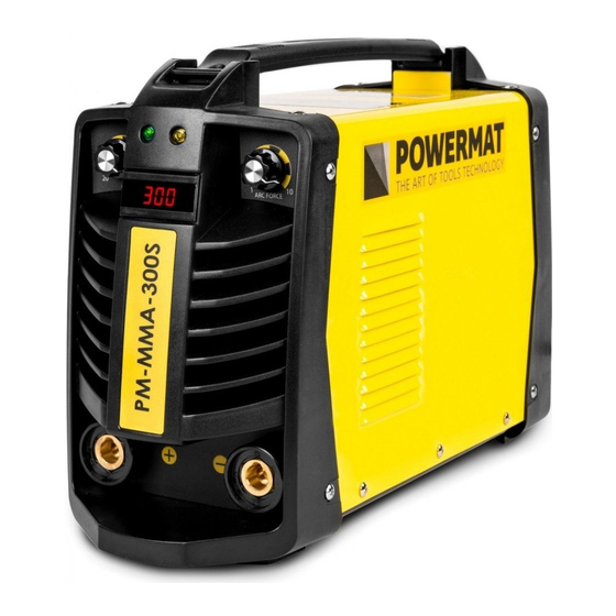
USER MANUAL
Inverter welder PM-MMA-250SP /
PM-MMA-300S
ORIGINAL INSTRUCTIONS
Table of
Contents
Previous
Page
Next
Page
1
2
3
4
5
Advertisement
Table of Contents
Need help?
Do you have a question about the PM-MMA-250SP and is the answer not in the manual?
Ask a question
Questions and answers
Related Manuals for Powermat PM-MMA-250SP
Welding System Powermat PM-MMA-300S User Manual
Inverter welder (20 pages)
Welding System Powermat PM-IMG-230T User Manual
Inverter welder (25 pages)
Welding System Powermat PM-IMGTS-210S User Manual
Inverter semi-automatic welding machine (34 pages)
Welding System Powermat PM-220L-IMGS User Manual
Inverter welder (33 pages)
Welding System Powermat PM-IMG-220L-PRO User Manual
Inverter welder (28 pages)
Welding System Powermat PM-IMG-220G User Manual
Inverter welder (26 pages)
Welding System Powermat PM-IMG-210S User Manual
Inverter welder (22 pages)
This manual is also suitable for:
Pm-mma-300s
Table of Contents
Print
Rename the bookmark
Delete bookmark?
Delete from my manuals?
Login
Sign In
OR
Sign in with Facebook
Sign in with Google
Upload manual
Upload from disk
Upload from URL


Need help?
Do you have a question about the PM-MMA-250SP and is the answer not in the manual?
Questions and answers