
Related Manuals for Powermat PM-IMG-220L-PRO


Summary of Contents for Powermat PM-IMG-220L-PRO
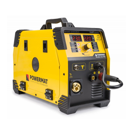
- Page 1 USER MANUAL PLACE PHOTO HERE Inverter Welder PM-IMG-220L-PRO ORIGINAL INSTRUCTIONS...
-
Page 2: Table Of Contents
Table of Contents SYMBOLS WARNING / INFORMATION ..................3 APPLICATION EQUIPMENT ......................... 3 TECHNICAL DATA ..........................4 SAFETY ........................... 4 GENERAL THOUGHTS ............................4 Safety during welding ....................4 ..Electromagnetic field .......... - Page 3 Maintenance ............................24 Malfunctions welding ........................ 24 Service ....................Error! Bookmark not defined. Service ....................Error! Bookmark not defined. REMOVAL OF USED ......................25 COMPANY INFORMATION ..........................26 DECLARATION OF CONFORMITY ........................26...
-
Page 4: Symbols Warning / Information
Powermat service ul. Defenders of the Gdansk Post 97 42-400 Zawiercie Tel. 32 670 39 68 4 internal e-mail serwis@powermat.pl REMOVAL OF USED Tel. 32 670 39 68 4 internal e-mail serwis@powermat.pl REMOVAL OF USED Error! You can Error! You can not find the source references. - Page 5 For safety reasons, the device can not be used by children and adolescents under the age of 18 and by persons under the influence of alcohol, drugs or other intoxicants. Persons who are not familiar with this manual, please read carefully before its first use.
-
Page 6: Technical Data
TECHNICAL DATA Model: PM-IMG-220L-PRO Welding method MIG / MAG Power 230V / 50Hz 6,1kVA 5,8kVa Power consumption Welding current range 40-220A 20-170A Range of welding voltage 16-25V 170A 132A Welding current duty cycle of 100% Welding current 60% duty cycle... -
Page 7: Electromagnetic Field
ARC RAYS CAN BURN: It is not allowed to look directly at the eyes uncovered and exposed to an ARC RAYS CAN BURN: It is not allowed to look directly at the eyes uncovered and exposed to an electric arc. Always wear a mask or helmets protected with a suitable filter. Bystanders, nearby, protected with non-combustible, absorbing radiation screens. - Page 8 FIRE OR EXPLOSION: Do not use the machine near flammable substances. Make sure that the FIRE OR EXPLOSION: Do not use the machine near flammable substances. Make sure that the electrical network is properly configured to work with the welder. Overloading the power supply may cause fire.
-
Page 9: Pacemakers
CYLINDER MAY EXPLODE: Use only approved cylinders properly operated regulator. CYLINDER MAY EXPLODE: Use only approved cylinders properly operated regulator. Transported and stored in an upright position only. Protect from heat sources, tipping and mechanical damage. Keep in good condition all the elements of the gas. OLE ELECTROMAGNETIC OLE ELECTROMAGNETIC To reduce the amount of electromagnetic fields in the workplace include:... -
Page 10: Description Of The Device
DESCRIPTION OF THE DEVICE FRONT PANEL Control switch voltmeter / Connector cable polarity ammeter Socket polarity (+) Voltmeter (MIG) Control knob (wire feed) Socket polarity (-) Ammeter Socket welding torch MIG / MAG Command socket holder with built-in wire feeder and the magazine Welding process selecting switch (SPOOL GUN) Stick function switch wire 16. -
Page 11: Description Of Symbols On The Label
DESCRIPTION OF SYMBOLS ON THE LABEL Current (DC) single phase alternating current (AC) of the rated frequency 50Hz Symbol and 60Hz operating frequency. Nominal input voltage (AC) Nominal input voltage (AC) Nominal input voltage (AC) Maximum input current Maximum input current Maximum input current 1max 1max... -
Page 12: Welding Service
Warning! It is forbidden to use the device or completely dismantled the housing removed, it may cause electric shock Warning! It is forbidden to use the device or completely dismantled the housing removed, it may cause electric shock and lead to severe injury. Do not touch the energized equipment. Before installing the unit, check electrical network to which the device is connected meets the requirements placed on the nameplate and that it meets all local and national standards. - Page 13 Fig. 1 of the connection device deterministic (for welding shield Connect a gas cylinder in accordance with the drawing of gas into the socket so the device) Attaching the welding wire 1. Before the spool of wire, make sure that the roller drive unit 1.
-
Page 14: Welding Mma
Connection of protective gas 1. The bottle of carefully selected protective gas must be set on the shelf and semi-automatic 1. The bottle of carefully selected protective gas must be set on the shelf and semi-automatic secured by a chain. 2. -
Page 15: Mig
supplying METHOD supplying METHOD supplying METHOD MIG - welding process, wherein the shielding gas used is chemical inert gas, for example. Argon, helium. MIG - welding process, wherein the shielding gas used is chemical inert gas, for example. Argon, helium. 1. -
Page 16: Mig
supplying METHOD supplying METHOD supplying METHOD During welding, the torch moves the welding wire, which is constantly melting in an electric arc. The fluid material of the welding wire connected to a combination of material to form a liquid weld pool. When moving the welding torch, lake follow, to solidify at the edges and creating a durable combination of materials. - Page 17 Among the many possible methods of carrying the torch frequently used zig-zag movements pushed, which are aimed at keeping the bow in the direction of welded components. Method Front, which is pushing the burner is better than the method from the rear (pulling burner) due to increased shielding gas coverage, and introduces joint on each edge of the materials to be joined, resulting in a flat and neat seam.
- Page 18 oxidising recommended only welding steel WHAT WHAT down low carbon oxidising Recommended only for welding carbon steel and low-alloy Ar + 20 - 50% of CO2 steel oxidising Recommended only for welding carbon steel and low-alloy Ar + 10% CO Ar + 10% CO Ar + 10% CO Ar + 10% CO...
-
Page 19: Basic Information For Welding Mma
5. You can start the process of welding. 5. You can start the process of welding. 6. After welding is complete, move the electrode from the work piece and set 6. After welding is complete, move the electrode from the work piece and set OFF switch in the OFF position. -
Page 20: Welding Electrodes In Practice
Setting the welding current is dependent on the diameter of the electrode size and thickness of the welded material and the welding position. When welding materials with the same thickness, materials with a small area is used lower electrode and a lower welding current than for larger surfaces. Thin metal requires less power, and smaller electrode requires less power. -
Page 21: Electric Arc Welding
Supplying ELECTRIC ARC Supplying ELECTRIC ARC Fig. 4 Figure 4. Presents phenomena occurring during arc welding, which is greatly enlarged what is seen by the welder. Figure 4. Presents phenomena occurring during arc welding, which is greatly enlarged what is seen by the welder. Curved space is shown in a central position in the picture. -
Page 22: Correct Welding Position
differences in the types of buffer zones to gain knowledge select the right electrode for the job. When choosing the electrodes need to consider: 1. Implementation example. Steel, mild steel and stainless steel. 1. Implementation example. Steel, mild steel and stainless steel. 2. -
Page 23: Proper Arc Length
ARC LENGTH RAWIDŁOWA ARC LENGTH RAWIDŁOWA Arc length is the distance from the end of the electrode to the workpiece. Once the arc is stabilized setting proper arc length is very important. Arc should have a length of approximately 1.5 - 3mm. Due to the burning of the electrodes must be kept adjust the length of the arc. -
Page 24: Base Metals
Etal BASE Etal BASE Most metals found in farms and small shops are low carbon steel, sometimes offered mild steel. Typical items made with this type of steel is the most common metal plates, pipes, rolling, angles, beams. This type of steel can usually pospawać... -
Page 25: Welding Parameters Draw
Shielding gas not only protects the tungsten electrode and the welding area before access gases from the atmosphere, but also determines the parameters such as energy 9napięcie arc welding), weld shape, and even the chemical composition of the weld. Shielding gas should be selected depending on the work piece and the desired characteristics of the weld shown in the following table: The type of welded metal shielding gas welding properties Argon... -
Page 26: Maintenance And Service
MAINTENANCE AND SERVICE REPLACEMENT NOTE! REPLACEMENT NOTE! REPLACEMENT NOTE! The electrical shock can cause serious injury or even death. Under no circumstances The electrical shock can cause serious injury or even death. Under no circumstances The electrical shock can cause serious injury or even death. Under no circumstances may touch parts under voltage wiring such as terminals or the internal components of the device. -
Page 27: Service
Repair of power tools should only be done by qualified personnel using original spare parts. This ensures the safety of the device. Address: Powermat service ul. Defenders of the Gdansk Post 97 42-400 Zawiercie Tel. 32 670 39 68 4 internal e-mail serwis@powermat.pl... -
Page 28: Company Information
You can also refer to the old appliance collection point. For more information on the collection system equipment is at hand: https://sklep.powermat.pl/webpage/pl/recycling.html COMPANY DETAILS PH Powermat TMK Bijak Sp. General Partnership Ul. Defenders of the Gdansk Post 97 42-400 Zawiercie http://www.powermat.pl DECLARATION OF CONFORMITY...
Need help?
Do you have a question about the PM-IMG-220L-PRO and is the answer not in the manual?
Questions and answers