Advertisement
Quick Links
Assembly Instructions
Assembly Instructions
Important
Before you begin, read and comply with all safety and operating instructions,
and ensure all parts and correct quantities are included.
Any parts damaged during shipment must be reported within 5 days of receipt.
To report information regarding missing parts or damage, to purchase parts or
accessories, or if you have any questions, please contact us.
www.spectrumfurniture.com
800-235-1262, 715-723-6750
Thank you for purchasing Spectrum products!
Parts will be for 36", 44", 60", or 72"W depending on size ordered.
(1) Worksurface
(1) 0174258
Left leg
(2) 0174452
Leg cover
(1) Cord channel
front
(1) Cord channel
bottom
(1) Top cover
Assembly tip: Do not tighten component fasteners completely
(1) 0174681
until all have been installed. Keeping them loose will help with
Right leg
alignment between parts during assembly.
Legs are factory-assembled for a 28"H worksurface but are adjustable
from 24"-30"H (in 2" increments). If a different worksurface height is
needed, remove the 4 screws in each leg, re-adjust to the new height, and
re-install screws. Make sure both legs are set to the same height.
(1) Modesty
panel
(1) Stretcher
GG Gaming Desk
(36", 44", 60" and 72"W)
37421
X2
Leg height
(8) 035728
1/4-20 x 1/2"
PHMS
(4) 037779
5/16-18 x 1"
Glide
(1) 0176848
Unit-to-unit
bracket
(10) 0100167
8-32 x 1/2" PH
Thrd ctg screw
(13) 0101382
#14 x 7/8" PHSM
(1) 0176830
Tab
(1) 025069
Glide Wrench
0193831 Page 1 of 7
Advertisement

Subscribe to Our Youtube Channel
Related Manuals for Spectrum GG Gaming Desk 37421


Summary of Contents for Spectrum GG Gaming Desk 37421
- Page 1 800-235-1262, 715-723-6750 Thank you for purchasing Spectrum products! Parts will be for 36”, 44”, 60”, or 72”W depending on size ordered. GG Gaming Desk (36”, 44”, 60” and 72”W)
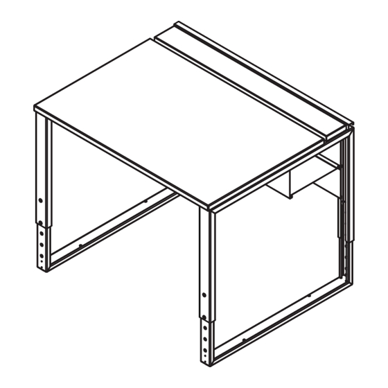
- Page 2 Attach legs to worksurface Right leg 1. Place the worksurface face-down onto a non-abrasive surface. 2. There is a left and right leg. Orient each leg with the screw hole (next to bumper) on the outside edge of the worksurface. 3.
- Page 3 Attach cord channel 1. Attach the front cord channel to the worksurface with #14 x 7/8” PHSM screws. (3 or 4 depending on desk width). Install (1) 1/4-20 x 1/2” PHM screw into each leg. 2. Hook the cord channel bottom tabs into the cord channel front slots. 3.
- Page 4 Install top cover screws (optional) Flip desk upright 1. Carefully flip the desk upright. This will require at least two people. These screws help keep the top cover in place. 1. Install (1) 8-32 x 1/2” PH Thrd ctg screw on the outside hole on the top of the leg (next to the rubber bumper).
- Page 5 Install top cover panel 1. Set the top cover over the rubber bumpers. Top cover panel Slide the top cover panel forward. Cords and wires can be routed through the gap behind. If a monitor arm will be clamped to the worksurface, slide the top cover panel back.
- Page 6 Connecting desks together (optional) Behind front legs (2) 1/4-20 x 1/2” PHMS Unit-to-unit bracket Installing LED strip light tape (optional) Note: Access ports are provided at the top of the audience-side panel that provide the ability to route customer-supplied LED strip light tape inside the top channel.
-
Page 7: Warranty
P.A.C.E. program (Product Assur- ance to meet Customer Expectations). We expressly warrant that Spectrum products will be of good quality and workmanship and free from defect for the period set out in the warranty from the date of delivery.
Need help?
Do you have a question about the GG Gaming Desk 37421 and is the answer not in the manual?
Questions and answers