Table of Contents
Advertisement
Quick Links
Advertisement
Table of Contents

Subscribe to Our Youtube Channel
Related Manuals for SUPMEA U-0003NR-EN1


Summary of Contents for SUPMEA U-0003NR-EN1
- Page 1 User's Manual Paperless Recorder U-0003NR-EN1...
- Page 2 We try our best to guarantee that the manual content is accurate, if you find something wrong or incorrect, please contact us. This product is forbidden to use in explosion-proof occasions. Version U-0003NR-EN1...
- Page 3 Safety Precautions In order to use this product safely, be sure to follow the safety precautions described. About this manual Please submit this manual to the operator for reading. Please read the operation manual carefully before applying the instrument. ...
- Page 4 The following safety signs are used in this manual: Hazard, if not taken with appropriate precautions, will result in serious personal injury, product damage or major property damage. Warning:Pay special attention to the important information linked to product or particular part in the operation manual. Confirm if the supply voltage is in consistent with the rated voltage before ...
- Page 5 Please check the grounding protection status regularly. Do not operate if you think that the protection measures such as grounding protection and fuses are not perfect. Ventilation holes on the product housing must be kept clear to avoid malfunctions due to high temperatures, abnormal operation, shortened life and fire.
- Page 6 Disclaimer The company does not make any guarantees for the terms outside the scope of this product warranty. This company is not responsible for damage to the instrument or loss of parts or unpredictable damage caused directly or indirectly by improper operation of the user.
-
Page 7: Table Of Contents
Contents Chapter 1 Introduction .................1 1.1. Overview ..................1 1.2. Main parameters ................2 1.3. Input signal ..................2 1.4. Output signal .................. 3 1.5. Other parameters ................4 Chapter 2 Installation & Wiring ..............5 2.1 Unpacking ..................5 2.2 Installation ..................5 2.3 Wiring .................... -
Page 8: Chapter 1 Introduction
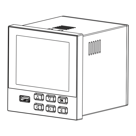
Chapter 1 Introduction Chapter 1 Introduction 1.1.Overview This product is an industrial paperless recorder equipped with a 3.5-inch TFT true color full view LCD display screen. Multiple types of industrial standard signals such as current, voltage, thermocouples, and thermal resistors can be connected to achieve temperature, humidity, pressure, liquid level, flow display, recording, over limit monitoring, reporting, data communication, signal transmission, flow accumulation, flow temperature and pressure compensation, and other functions. -
Page 9: Main Parameters
Chapter 1 Introduction 1.2.Main parameters Table 2 The main parameters 3.5-inch TFT true color LCD screen. Screen size Resolution is 320 * 240 High definition LED backlight. Dimension:96mm×96mm×100mm Dimension Cutout dimension:92mm×92mm Panel thickness 1.5mm~6.0mm Weight 0.37kg (85~264)VAC,(47~63)Hz Power supply (24VDC can be customized) 64M Bytes Flash Internal storage (96M,128M can be customized) -
Page 10: Output Signal
Chapter 1 Introduction Table 4 Thermocouple input(not include cold junction error) Type Measure range(℃) The maximum allowed error(℃) 600 ~ 1800 ±2.4 -200 ~ 1000 ±2.4 -200 ~ 1200 ±2.4 -200 ~ -100 ±3.3 -100 ~ 1300 ±2.0 -50 ~ 100 ±3.7 100 ~ 300 ±2.0... -
Page 11: Other Parameters
Chapter 1 Introduction Table 7 Current output Type Range (mA) Maximum permissible error (mA) 4 ~ 20 ±0.025 Current output 0 ~ 20 ±0.025 0 ~ 10 ±0.025 1.5.Other parameters Table 8 Other parameters Power distribution 150mA, 24 VDC. specifications All data is stored in Flash storage to make sure that all historical data and configuration parameters are Power failure protection... -
Page 12: Chapter 2 Installation & Wiring
Chapter 2 Installation & Wiring Chapter 2 Installation & Wiring This chapter describes the installation and wiring methods of this instrument. It is necessary for technicians to learn when they use the instrument for the first time. This is a procedure which enables the instrument to normal operation,as the table Unpacking Installation Wiring... - Page 13 Chapter 2 Installation & Wiring Indoor installation Operating temperature:(0~50)℃ Relative humidity:10%~85% (No condensation) Ventilation requirements: ventilated to prevent the internal meter temperature is too high Vibration disturbance:Less mechanical vibration Air ingredients: NOT easy to produce condensate, non-corrosive gas or ...
-
Page 14: Wiring
Chapter 2 Installation & Wiring Installation diagram Mounting 安装支架 安装支架 安装支架 Installation bracket +0.5 front 前 前 前 panel 面 面 面 板 板 板 installation screw 安装螺钉 安装螺钉 安装螺钉 Unit: mm 单位:mm Figure 2 Product dimension and installation drawing 2.3 Wiring In order to improve the stability and accuracy of the signals, it is recommended that you use the cold terminal signal cable to wire. - Page 15 Chapter 2 Installation & Wiring Figure 4 Terminal view of updated type NOTE: The analog quantity output board needs an external 24V power supply, which can be provided by the power adapter accompanied with the product. As the power is large, please do not power any other transmitter at this time.
- Page 16 Chapter 2 Installation & Wiring Table 9 Specific instructions of each terminal Terminal No. Signal type Description 24VDC power supply: L is 24V+; N is 24V-; E is undefined. AC Power((single-phase three E,N,L E,N,L wire system) terminal block: L is Phase line terminals, N is Zero line terminals, E is Ground terminal.
- Page 17 Chapter 2 Installation & Wiring Terminal No. Signal type Description 485- communication port RS-485 Distribution output 24V+ 24V- Alarm output Terminal Description Relays Alarm output Channel 1 Relays Alarm output Channel 2 Relays Alarm output Channel 3 Relays Alarm output Channel 4 Alarm Commons Table 10 Instructions for updated type terminal Terminal No.
- Page 18 Chapter 2 Installation & Wiring 2.3.2 Wiring diagram Figure 5 24V Wiring diagram Figure 6 220V Wiring diagram...
- Page 19 Chapter 2 Installation & Wiring 2.3.3 Wiring of signal cable mA input (without power distribution) mA input (with power distribution) V/mV input TC input RTD input Figure 7 Schematic diagram of signal cable...
-
Page 20: Chapter 3 Basic Operation
Chapter 3 Basic Operation Chapter 3 Basic Operation Figure 8 Panel component distribution Panel component distribution of paperless recorder is shown in figure 8. 3.1 Panel component LCD Screen:Display monitor and configuration. key: Table 11 Key definition Name of key Name of key Name of key Down... -
Page 21: Navigation Keys
Chapter 3 Basic Operation 3.2 Navigation keys 3.2.1 Display interface Table 12 Screen Operation Information bar Screen Description Loop display: Indicates the on state of the loop display mode on the patrol display interface. Alarm: When there is an alarm Loop display message appears, please enter the alarm screen to check it and... - Page 22 Chapter 3 Basic Operation Loop display screen Screen Description Display channel bit number, the instantaneous value, original signal bar graph and alarm status. Pressing up/down-key can switch channel. You can switch the former and later picture through left key and right key.
- Page 23 Chapter 3 Basic Operation Flow screen Screen Description Display items of flow channel: instantaneous value, accumulation value, unit and alarm state. Press left/fight key can switch the previous and the current interfaces. Accumulation screen Screen Description Display instantaneous value and total accumulation value at the same time.
- Page 24 Chapter 3 Basic Operation 3.2.2 Query interface Table 13 Screen Operation Enter the query Screen Description Press and hold the OK key in the display interface to enter the configuration interface. Press the up/down keys to select the cursor position, and press the confirm key to enter the corresponding function.
- Page 25 Chapter 3 Basic Operation Powerdown record Screen Description Pressing up/down-key can switch previous and next item Pressing left/right key can switch the former and later page Operation log Screen Description Pressing up/down-key can switch previous and next item. ...
- Page 26 Chapter 3 Basic Operation of records, the [Cfg] folder contains configuration files, the [History] folder contains historical records, and the [Info] folder contains various types of information (such as alarm information). Table 14 File name Document Subdirectory File name Historic record /History H220905091650.csv/ H220905091650.mda...
-
Page 27: Chapter 4 Configuration
Chapter 4 Configuration Chapter 4 Configuration This chapter introduces the individual configuration parameters of instrument. Figure 9 Configuration interface 4.1.System setting Figure 10 System setting interface Configuration Item Description: Table 16 System setting configuration item description Configuration Item Function Description Parameter range 10-bit character string Device Name... - Page 28 Chapter 4 Configuration Configuration Item Function Description Parameter range Interval Set record interval 1s,2s,5s...60min Language Select system language Chinese/English Set cold compensation Cold Compensation Auto / Manual mode Compensation Temp Value -50~110 temperature (℃) Set the atmospheric Air Pressure 0~999999 pressure coefficient Display cycling time by Group Cycle...
-
Page 29: Input Setting
Chapter 4 Configuration 4.2.Input setting Figure 11 Input setting interface Configuration Item Description: Table 18 Input setting configuration item description Configuration Item Function Description Parameter range AI01~AI18 Channel Select analog channel (The real display shall prevail.) Current,Vol-V,Vol-mV,TC,RTD Type Set signal types (4~20)mA,(0~20)mA,(0~10)mA ,Pt100,Pt1000,Cu50,(1~5)V,(0 ~10)V,(0~5)V,B,E,J,K,S,T,R,N,... - Page 30 Chapter 4 Configuration Configuration Item Function Description Parameter range Multiple display modes are Displays the value of available, such as upper limit Broke channel broke value, lower limit value, and hold Enter to alarm setting Alarm screen. Copy Copy the configuration Paste the copied Paste configuration...
-
Page 31: Output Setting
Chapter 4 Configuration Configuration Item Function Description Parameter range shall prevail.) Alarm LL Lower alarm value -999999~999999 Disable,Realy1,Realy2,Real Lower alarm output Output LL y3,Realy4 (The real display terminal shall prevail.) Relay delay time 0~120s Relay delay Alarm Hysteresis 0~999999 Hysteresis Note: The relay delay and hysteresis of different alarm types are independently set. - Page 32 Chapter 4 Configuration Figure 13 Output setting interface Configuration Item Description: Table 20 Output setting configuration item description Configuration Item Function Description Parameter range Channel Select AO channel 01~04 Enable/Disable this State Enable/Disable channel Source Channel to be output AI01~AI18,FLOW1~FLOW4, Output analog quantity (4~20)mA, (0~20)mA, Signal...
-
Page 33: Function Setting
Chapter 4 Configuration 4.4.Function setting Figure 14 Function setting interface 4.4.1 Communication setting This product supports the communication operation with the upper computer (the supporting upper computer can be obtained from the company's official website) to achieve real-time monitoring of the instrument. This product only supports the Modbus RTU protocol. - Page 34 Chapter 4 Configuration 4.4.2 Data Clear Figure 16 Data clear interface Configuration Item Description: Table 22 Data clear configuration item description Configuration Item Function Description Clear Alarm list Clear all alarm information Clear Operation list Clear all operation records Clear Powerdown list Clear all powerdown records Clear Acc report Clear all accumulated records...
-
Page 35: Flow Setting
Chapter 4 Configuration Configuration Item Description: Table 23 U disk operation configuration item description Configuration Item Function Description File format Export Config Export current recorder configuration CFG(.cfg) Import Config Read recorder configuration in U disk Operation list Export operation list Firmware Update Firmware Update Format USB... - Page 36 Chapter 4 Configuration Configuration Item Function Description Parameter range Source Channel of flow signal AI01~AI18 Select the number of Decimal decimal places for flow Low limit of range after flow Range L -999999~999999 compensation High limit of range after flow Range H -999999~999999 compensation...
- Page 37 Chapter 4 Configuration Table 25 Flow model and formula � � � = Flow model Formula � � No extraction of a root No extraction of a root for differential pressure Extraction of a root for differential pressure ...
-
Page 38: Accumulation Setting
Chapter 4 Configuration 【Note 3】: *Q*H heat heat Where: Qheat: Heat flow rate Kheat: Heat flow rate coefficient (The coefficient of enthalpy of this recorder is 1) Q: Mass flow rate H: Enthalpy 4.6.Accumulation setting The accumulation function accumulates selected signal sources in terms of hour, day, and month, which forms a time report, a daily report, and a monthly report. - Page 39 Chapter 4 Configuration Configuration Item Function Description Parameter range Accumulative InitVal Initial value at restoration -999999~999999 Reset this channel according to 【Note 1】 Reset Acc InitVal accumulated initial value 【Note 1】:After modifying the accumulated initial value, it requires to enable the configuration again to make it effective.
-
Page 40: Chapter 5 Fault Handling And Maintenance
Chapter 5 Fault Handling and Maintenance Chapter 5 Fault Handling and Maintenance In order to maintain the reliability of the instrument and maintain its good working condition for a longer period of time, please regularly inspect and maintain it to ensure that the installation and usage environment of the instrument meet the requirements, and conduct wiring and other operations according to normal procedures. - Page 41 Chapter 5 Fault Handling and Maintenance 5.2.2 Signal data display error Check if the 否 input signal line Correct wiring according to 2.3 is connected correctly? Configuration settings and related items such as signal source, signal Check if the type, range, signal cutoff, and configuration is linear correction may all cause correct?
-
Page 42: Chapter 6 Warranty & After-Sales Service
Chapter 6 Warranty & After-sales Service Chapter 6 Warranty & After-sales Service We promise to the customer that the hardware accessories provided during the supply of the instrument have no defects in material and manufacturing process. From the date of the purchase, if the user's notice of such defects is received during the warranty period, the company will unconditionally maintain or replace the defective products without charge, and all non customized products are guaranteed to be returned and replaced within 7 days. -
Page 43: Appendix A: Communication
Appendix A: Communication Appendix A: Communication Table 28 Modbus Address Register Functio Acces Name Description address n code s Type Note the byte order. The Channel 1 Quantities 0x2000 0x03 float default is 4321 Channel 2 Quantities 0x2002 0x03 float ……………... - Page 44 Appendix A: Communication Register Functio Acces Name Description address n code s Type State of flow channel 1 0x2153 0x03 short Total accumulation Accumulated value integer value of accumulated 0x22C0 0x03 long part channel 1 Total accumulation Accumulated value integer value of accumulated 0x22C2 0x03...
- Page 45 Appendix A: Communication Register Functio Acces Name Description address n code s Type Monthly accumulation value of accumulated 0x23B0 0x03 float channel 1 Monthly accumulation value of accumulated 0x23B2 0x03 float channel 2 Monthly accumulation value of accumulated 0x23B4 0x03 float channel 3 Monthly accumulation...
-
Page 46: Appendix B: Calculation Of Flow Coefficient K
Appendix B: Calculation of flow coefficient K Appendix B: Calculation of flow coefficient K Case 1: Orifice (no extraction of a root for differential pressure), measure the flow of oxygen in Nm3/h. Calculation sheet process data: design norm Einheit absolute 950.000 pressure temperature... - Page 47 Appendix B: Calculation of flow coefficient K Calculation method: The oxygen density under standard conditions and design temperature pressure are calculated. According to the ideal state equation: The density under standard conditions is 1.429Kg/m The density under design temperature pressure is 12.485Kg/m ...
Need help?
Do you have a question about the U-0003NR-EN1 and is the answer not in the manual?
Questions and answers