Table of Contents
Advertisement
Quick Links
Headquarters
5th floor,Building 4,Singapore Hangzhou Science Technology Park,No. 6 street,
Hangzhou Economic Development Area,Hangzhou 310018,China
Singapore
2 Venture Drive #11-30 Vision Exchange Singapore
info@supmea.com
www.supmea.com
Supmea Automation Co.,Ltd.
User Manual
Ultrasonic flowmeter
U-SUP-2000H-EN1
Advertisement
Table of Contents

Related Manuals for SUPMEA SUP-2100H Series


Summary of Contents for SUPMEA SUP-2100H Series
- Page 1 User Manual Ultrasonic flowmeter Headquarters 5th floor,Building 4,Singapore Hangzhou Science Technology Park,No. 6 street, Hangzhou Economic Development Area,Hangzhou 310018,China Singapore 2 Venture Drive #11-30 Vision Exchange Singapore info@supmea.com www.supmea.com U-SUP-2000H-EN1 Supmea Automation Co.,Ltd.
- Page 2 Preface Thank you for purchasing our product. This manual is about the various functions of the product, wiring methods, setting methods, operating methods, troubleshooting methods, etc. Please read this manual carefully before operation, use this product correctly to avoid unnecessary losses due to incorrect operation. After you finish reading, please keep it in a place where it can be easily ...
- Page 3 Safety Precautions In order to use this product safely, be sure to follow the safety precautions described. About this manual Please submit this manual to the operator for reading. Please read the operation manual carefully before applying the instrument. ...
- Page 4 Do not modify this product.The following safety signs are used in this manual: Hazard, if not taken with appropriate precautions, will result in serious personal injury, product damage or major property damage. Warning:Pay special attention to the important information linked to product ...
- Page 5 fire accident. Please check the grounding protection status regularly. Do not operate if you think that the protection measures such as grounding protection and fuses are not perfect. Ventilation holes on the product housing must be kept clear to avoid ...
- Page 6 Disclaimer The company does not make any guarantees for the terms outside the scope of this product warranty. This company is not responsible for damage to the instrument or loss of parts or unpredictable damage caused directly or indirectly by improper operation of the user.
-
Page 7: Table Of Contents
Content Chapter 1 Introduction ..................... 1 1.1 Preface ......................1 1.2 Features ....................2 1.3 Principle of Measurement ................. 2 1.4 Parts identification ..................3 1.5 Typical Applications .................. 6 1.6 Data lntegrity and Built.in Time.Keeper .............7 1.7 Product ldentification .................7 1.8 Specifications .................... 7 Chapter 2 Starting Measurement ................ - Page 8 3.2 How to determine the direction of liquid flow in the pipeline ....20 3.3 How to change the measurement unit system ........20 3.4 How to select the flow unit ..............20 3.5 How to select the accumulator multiplier ..........20 3.6 How to open and close the accumulator ..........
- Page 9 Chapter 6 Communication Protocol ...............36 6.1 General ....................36 6.2 Interface Pin.out Definition ..............36 6.3 The Protocol ....................37 6.3 Protocol Prefix Usage ................38 6.4 Codes for the Keypad ................39 Chapter 7 Warranty & After-sales Service .............41 VIII...
-
Page 10: Chapter 1 Introduction
The advanced circuit design, the integration of the latest semiconductors, the user-friendly software interface both in English and Chinese languages and small-sized PCB board, all these features combine to make the SUP-2100H series ultrasonic flow meter the best and the biggest seller on the market. -
Page 11: Features
The difference in the transit time measured is directly and exactly related to the velocity of the liquid in the pipe, as shown in Figure l. www.supmea.com... -
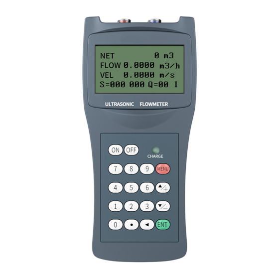
Page 12: Parts Identification
Tup is the time for the beam from upstream transducer to the downstream one Tdown is the time for the beam from downstream transducer to the upstream one ΔT=Tup -Tdown 1.4 Parts identification Converter: www.supmea.com... - Page 13 Chapter 1 Introduction www.supmea.com...
- Page 14 Chapter 1 Introduction www.supmea.com...
-
Page 15: Typical Applications
1.5 Typical Applications The SUP-2100H flow meter can be virtually applied to a wide range of measurements. The measured pipe ranges 20-6000 mm [0.5 - 200 inch]. A variety of liquid applications can be accommodated: ultra-pure liquids, potable water, www.supmea.com... -
Page 16: Data Lntegrity And Built.in Time.keeper
An improper time value affects no other functions but the date totalizer. 1.7 Product ldentification Each set of the SUP-2100H series flow meter has a unique product identification or ESN written into the software that can only be modified with a special tool by the manufacturer. -
Page 17: Chapter 2 Starting Measurement
LED is off, the battery would be 98% recharged. since the charging current becomes tapered when the battery recharge is nearly completed, i.e. the charging current becomes smaller and smaller, therefore, there should be no over-recharging problem. That means the charging progress can last www.supmea.com... -
Page 18: Power On
By this step, the flow meter is going to find the best threshold of receiving signal. The user will see the progress by the number 1, 2, or 3, which are indicated on the right lower corner of the LCD display www.supmea.com... -
Page 19: Keypad
M00, M01, M02 . M99. There are 2 methods to enter certain menu window: (1) Direct going/entering. The user can press the key followed by two-digit number keys. For example, the menu window M11 is for the entering of pipe outer www.supmea.com... - Page 20 "Locked M47 Open' message is indicated on the lowest line of the LCD display, it means the modification operations is locked out. In such cases, the user should go to M47 to have the instrument unlocked first before any further modification can be made www.supmea.com...
-
Page 21: Menu Windows Arrangement
2.6 Steps to Configure the Parameters The following parameters need to be configured for a proper measurement: (1) Pipe outer diameter (2) Pipe wall thickness (3) Pipe materials (for non-standard pipe materials*, the sound speed for the material must be configured too) www.supmea.com... - Page 22 (7)Press key to enter M24 window, press key to enter the option selection mode, use key to scroll up and down to the proper transducer mounting method, and then press key. www.supmea.com...
-
Page 23: Transducers Mounting Allocation
An optimum location would be defined as a straight pipe length full of liquid that is to be measured. The piping can be in vertical or horizontal position. The following table shows www.supmea.com... - Page 24 Generally speaking, the closer to the room temperature, the better. (3) Take the pipe fouling into consideration. select a straight length of a relatively newer pipe. If the condition is not satisfying, consider the fouling thickness as part of the liner for a better result. www.supmea.com...
-
Page 25: Transducers Lnstallation
2.8 Transducers lnstallation The transducers used by the SUP-2100H series ultrasonic flow meter are made of piezoelectric crystals both for transmitting and receiving ultrasonic signals through the wall of liquid piping system. The measurement is realized by measuring the traveling time difference of the ultrasonic signals. -
Page 26: V-Method Installation
2.8.3 Z-method Installation Z-method is commonly used when the pipe diameter is between 300 millimeters and 500 millimeters 2.8.4 w-method Installation w-method is usually used on plastic pipes with a diameter from 10 millimeters to 100 millimeters www.supmea.com... -
Page 27: N-Method Installation
(3) Adjust the transducers both vertically and horizontally while checking the varying signal strength, stop at the highest position, and then check the transducers spacing to make sure the transducers spacing is the same as what the M25 shows. www.supmea.com... -
Page 28: Signal Quality
(3) If the transducers are installed properly in the right directions. (4) If the mounting location is good and if the pipe has changed shape or if there is too much fouling inside the pipes (5) Other poor conditions. www.supmea.com... -
Page 29: Chapter 3 How To Use
If the multiplication factor is too large, the accumulated pulses will be too slow, which will affect the work of other secondary instruments. 3.6 How to open and close the accumulator Use M34,M35 and M36 to turn the positive, negative and net accumulators on and off respectively. www.supmea.com... -
Page 30: How To Zero The Flow Accumulator
3.12 How to modify the meter coefficient (scale factor) calibration calibration The scale factor is the ratio of the "true flow" to the flow measured by the meter. The scale factor can be obtained from the real flow test of the calibration device. www.supmea.com... -
Page 31: How To Use Password Protection
The frequency range is set in window M68. For example: a pipeline flow range is 0~3000m3/h, the corresponding frequency signal 200~1000Hz is required to be output. The user enters 0 in window M68, 3000 in window M69, and 200 and 1000 in window M67 www.supmea.com... -
Page 32: How To Set The Cumulative Pulse Output
Enter the lower flow rate of 300 in window M73 as the #1 alarm trigger point. In window M74, enter the upper limit flow rate of 2000 as the #2 alarm trigger point. Select "6. #1 Alarm" in window M77 www.supmea.com... -
Page 33: How To Use The Buzzer
3.24 How to use the work timer The Work Timer allows you to time an operation, for example, how long the battery will continue to operate when fully charged. Press ENT in the M82 window and select "Yes" to reset the timer. www.supmea.com... -
Page 34: How To Use The Manual Accumulator
Use window M+4 to view the total number of power failures since the meter was shipped. 3.27 How to know the operating time of the remaining battery power Check in window M07, see section s.2.1 for instructions. 3.28 How to charge the battery In chapter 2.1 for instructions. www.supmea.com... -
Page 35: Chapter 4 Menu Window Details
Window for entering the outer perimeter of the pipe Window for entering the outer diameter of the pipe 0 to 6000mm is the allowed range of the value Window for entering pipe wall thickness Window for entering the inner diameter of the pipe www.supmea.com... - Page 36 (6)Propane at -45C (7) Butane at 0C (8)0ther liquids (9) Diesel oil (10)Caster oil(11)Peanut oil (12) #90 Gasoline (13) #93 Gasoline (14) Alcohol (15) Hot water at 125C Window for entering the fluid sonic velocity only for non.standard liquids Window for entering the viscosity of the non.standard liquids www.supmea.com...
- Page 37 6. USA liquid barrel (bal) 7. Imperial liquid barrel (ib) 8. Oil barrel (ob) The flow unit in terms of time can be per day, per hour, per minute or per second. so there are 36 different flow rate units in total. www.supmea.com...
- Page 38 Network environment Identification Number. Any integer can be entered except 13(0DH, carriage return), 10 (0AH, 1ine feeding), 42 (2AH), 38, 65535. Every set of the instrument in a network environment should have a unique IDN. Please refer to the chapter for communication. www.supmea.com...
- Page 39 Display Version information and Electronic serial Number (ESN) that are unique for each 2100H series flow meter. The users can employ the ESN for instrumentation management RS-232 setup. Baud rate can be 75 to 115200 bps Not used Not used Not used www.supmea.com...
- Page 40 By selecting a proper input source, the OCT hardware will close when the trigger event occurs Not used Work as a keypad and display for another handhold set by RS-232 connected with the handset Not used Date totalizer Not used www.supmea.com...
- Page 41 RS-232C serial interface Browse the 64 recorded instrument power.on and power.off date and time with the flow rate at the time of power on and off Displays the total working time of the instrument Displays the last power.off date and time www.supmea.com...
-
Page 42: Chapter 5 Troubleshooting
Timer slow Error (1)Power on again timer.keeper or the Timer Fast Error (2)Contact with factory crystal oscillator. Number errors with the Initialize the calendar by Date Time Error calendar menu window M61 Reboot repetitively Hardware problems Contact the factory www.supmea.com... -
Page 43: Error Code And Counter.measures
Hardware problem Contact the factory Poor signal (1)Poor signal (1)Relocate measuring Detected detected place (2)Transducers (2)Clean the spot installed improperly (3)Check the cords (3)Too much fouling (4)Check the coupler (4)The pipe liners are too thick. (5)Problem with transducers cords www.supmea.com... -
Page 44: Other Problems And Solutions
The problems are likely caused by the user who has used the‘set Zero' function on this non-standstill flowing pipe. To solve this problem, use the‘Reset Zero' function on menu window M43. (2) The displayed flow rate is much lower or much higher than the actual flow rate www.supmea.com... -
Page 45: Chapter 6 Communication Protocol
Fuji's ultrasonic flow meter. 6.2 Interface Pin.out Definition for battery recharge, positive input not used OCT output not used for battery recharge, negative input RING input for connecting a MODEM www.supmea.com... -
Page 46: The Protocol
Force the FO output with a frequency in dddd Hz ESN(CR) Return the ESN for the Dddddddd(CR)(LF) instrument RING(CR) Handshaking Request by a M0DEM OK(CR) Response from a MODEM No action Command for GSM Please contact factory for detail www.supmea.com... -
Page 47: Protocol Prefix Usage
‘d' stands for the 0~9 digit numbers. *** @ stands for the key value, e.g., 30H for the‘0' key. 6.3 Protocol Prefix Usage (1) Prefix P The prefix P can be added before any command in the above table to have the www.supmea.com... -
Page 48: Codes For The Keypad
(then) all the following 3 values... (1) flow rate (2) velocity (3)POS totalizer...will be returned simultaneously. The combined command would be W4321DQD&DV&DI+(CR), and the result would be: +1.234567E+12m3/d(CR) +3.1235926E+00m/s(CR) +1234567E+0m3(CR) 6.4 Codes for the Keypad The codes for the keypad should be used when the instrument is connected with www.supmea.com... - Page 49 By this function, remote operation of this instrument can be realized, even via the Internet. Hexadecima1 Key Decimal Key code ASCII Code code ● 3BH,0BH MENU 3CH,0CH < 3DH,0DH > www.supmea.com...
-
Page 50: Chapter 7 Warranty & After-Sales Service
We promise to deal with the customer's technical questions within 2 hours. For the instruments returned to the factory for maintenance, we promise to issue the test results within 3 working days and the maintenance results within 7 working days after receiving them www.supmea.com...
Need help?
Do you have a question about the SUP-2100H Series and is the answer not in the manual?
Questions and answers