Table of Contents
Advertisement
Quick Links
Advertisement
Table of Contents

Related Manuals for SUPMEA SUP-5000C


Summary of Contents for SUPMEA SUP-5000C
- Page 1 Color Paperless Recorder Specification Paperless recorder SUP-5000C...
-
Page 2: Table Of Contents
Contents I. Overview............................1 II. Technical parameters........................1 Ⅲ. Precautions for use and installation....................2 31 Precautions for use........................ 2 3.1.1 Precautions for use of this instrument..............2 3.1.2 Precautions for using external storage media............3 3.2 Installation of instrument..................... 3 3.2.1 Sites of installation.....................3 3.2.2 Methods for installation.................... -
Page 3: Overview
I. Overview Color paperless recorder has 12-channel universal input (configurable selective input: standard voltage, standard current, thermocouple, thermal resistance, millivolt, etc.). It can be equipped with 12-channel alarming output or 6-channel transmitted output of analog quantity, RS485 communication interface, Ethernet interface, micro printer interface and USB interface, SD card socket;... -
Page 4: Ⅲ. Precautions For Use And Installation
measurement Display refresh 1 second cycle Setting mode The panel touch button is set; The parameter’s setting value is locked in password; The setting value is cut off for permanent storage. Display mode With 7 inch 800*480 dot matrix wide screen and TFT high brightness color graphics LCD display, LED backlight, clear screen, wide viewing angle. -
Page 5: Precautions For Using External Storage Media
cloth to wipe it. Benzene and banana water etc. should not be used for cleaning, which it may lead to discoloration or deformation. ●Please do not make the live parts approach the signal terminal, which may cause fault. ●Please do not impact this instrument. ●If you confirm that smoke, undesirable odor, abnormal noise and other abnormal situations occur from the instrument, please cut off the power supply immediately and contact the supplier or our company in time. -
Page 6: Methods For Installation
high temperature and humidity. If the temperature changes significantly, it will sometimes result in condensation of moisture. When the thermocouple is input, the measurement error will occur. At this time, please adapt to the surrounding environment for 1 hour or more and then continue using. ★If it is used at high temperature for a long time, the life of LCD will be reduced (... -
Page 7: Ⅳ. Functions And Operation Of The Instrument
●Installation of instruments (1) Methods for installation A. Put in the instrument from the front of the dashboard. B. Use the mounting support carried with the instrument, as shown in the right figure. ▲Fixed four mounting brackets on both sides of the instrument . -
Page 8: Switching Of Running Screens
operate the instrument conveniently without professional training. After the instrument is connected to the power supply, the initial screen of the system is displayed, the initialization system is completed, and thus the real-time curve screen is entered. The following will introduce each operation display screen and each configuration screen respectively. - Page 9 ①:Time scale: The duration of time expressed in each grid, and the time scale is related to the recording interval. Refer to the table below: Recording 15 S 30 S 1min 2 min 4 min interval 8min/gri 12min/g 30min/g 2min/grid 4min/gri 1h/grid 2h/grid...
-
Page 10: Bar Chart Screen
⑩: The display / hidden marks of curves: "√" indicates display of curve, if not, hide the alarming function , green indicates no alarming, red/pink indicates alarming. curve. (11): Operation keys: Press the “Switch” key to switch to other display screens. Press the “Time scale"... -
Page 11: Digital Display Screen
⑥ Operation keys: Press the" Switch” key to switch to other display screens. Press the "Preceding group" key to see the bar charts combinations of the previous group Press the "Latter group" key to see the bar charts combination of the latter group. Press the "Cycle"... -
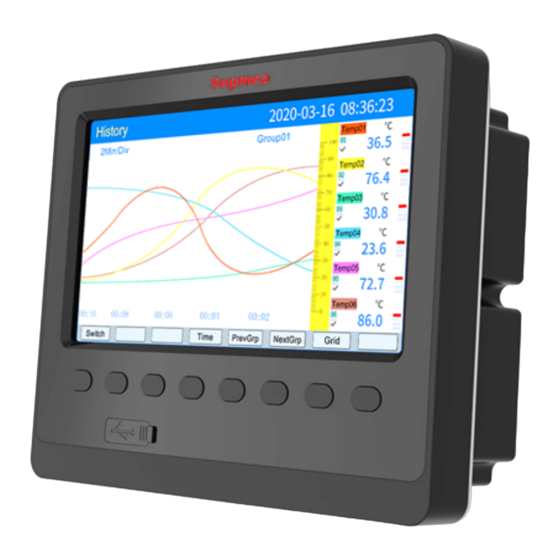
Page 12: Historical Curve Screen
Press the"Channel-12" key to display the bit number of channels, data of engineering quantity, alarming state and engineering unit of "Channel-12" simultaneously. Press the "Preceding group" key to see the digital display combinations of the previous group Press the "Latter group" key to see the digital display combination of the latter group. Press the "Cycle"... -
Page 13: Alarming List Screen
limit, high limit, low limit and low low limit of the over-limit alarming signs. Gray indicates no function of alarming, green indicates no alarming, red/pink indicates alarming. (11): The display / hidden marks of curves: "√" indicates display of curve, if not, hide the curve. -
Page 14: File List Screen
⑦: The current relay state, from left to right, they symbolizes in turn the current state of 1-12 limit relays, green indicates that the relay contacts are disconnected, red indicates that the relay ⑧: Operation keys: contacts are closed. Press the "Switch” key to switch to other display screens. Press the "Up shift”... -
Page 15: Printing Screen (In Case There Is The Printing Function, The Screen Is Available)
⑦: Record the total duration: Calculate the total duration of file records. Timing stopping: The file ends the record while coming to the set time. ⑧: The progress bars of the file’s storage capacity (Note: The record mode in the record ⑨: Operation keys: configuration appears when it is not circular). - Page 16 ⑦: Printing time interval: Select the time interval between data printings, the unit is the set ⑧: Operation keys: printing interval × recording interval (only valid for data printing). Press the "Switch” key to switch to other display screens. Press the "Up shift" key to move upwards the cursor, then press the "Enter" key to modify the cursor, and then press the "Enter"...
-
Page 17: Backup Screen (In Case There Is The Backup Function, The Screen Is Available)
Time Data --------------------------------------------------- 18-07-24 15:31:40 850 - -- measurement value of starting time 18-07-24 15:31:41 850 18-07-24 15:31:42 850 18-07-24 15:31:58 425 18-07-24 15:31:59 425 18-07-24 15:32:00 425 - -- measurement value of end time --------------------------------------------------- B. Timing printing The time interval and starting time for the timing printing are set in the system configuration. When the system time reaches the set interval time, the instrument will automatically control the printer for timing printing. - Page 18 name)/instrument date (year/month/day)/instrument time (hour/minute). In this operation screen, the user can back up the historical data of all channels recorded in the instrument to the flash or SD card, and input the backup data into the computer to reproduce, analyze and print the data through DTM, the software of the upper computer.
-
Page 19: Power-Off Screen
is not completed, press "Delete" key, the instrument will remind "deleted" backup data is stopped. When there is no SD card connection, there will be no SD card; when there is SD card connection, there will be no prompt, there will be corresponding icon display in the status bar; when there is no flash connection, there will be no flash prompt by pressing the "Backup"... -
Page 20: Configuration Screen
4.12 Configuration screen The password is made up of 6-digit number and *. Note: If the password is set wrong, the user will not be able to enter the configuration screen. The factory default password is 000000. The following will introduce each configuration screen: 4.12.1 System configuration ★Language selection: Simplified Chinese and English are optional. -
Page 21: Record Configuration
★Timing printing: Set the time for timing printing . ★Starting time: Set the starting time of timing printing. ★Alarming printing: On and Off are optional. ★Clear data: Clear all stored data in instrument memory, including historical data, alarming list, file list, power-off record. Operation: in this screen, Move the cursor according to the "Left shift"... - Page 22 Average value: The average value of real-time data between the recording points before and after The average value is calculated by weighted average method. Maximum value: Take the maximum value of the real-time data between the recording points before and after. Minimum value: Take the minimum value of real-time data between the recording points before and after.
-
Page 23: Display Configuration
4.12.3 Display configuration ★Closing LCD: You can select after 5, 10, 30 minutes, 1 hour, and never close. ★Cycle interval: Cycle shows the interval for next combination, 4 seconds, 8 seconds, 15 seconds, 30 seconds are optional. ★Boot screen: Boot screen can choose the real-time curve, bar chart screen, digital display screen, historical curve, file list, power-off record, before power-off. -
Page 24: Input Configuration
4.12.4 Input configuration ★Configuration channel: Select the number of channel for display configuration. ★Bit number: It indicates the bit number of the engineering corresponding to the display channel. As for the setting method, please refer to Section 4.12.4.1 Introduction to Input Method. ★Signal types: B, S, K, E, T, J, R, N, F2, Wre3-25, Wre5-26, Cu50, Cu53, Cu100, Pt100, BA1, BA2, 0 ~... - Page 25 99999 radication Wre3-25 ±20mV 0~2300℃ -9999~ 0~5V 99999 radication Wre5-26 ±100mV 0~2300℃ -9999~ 1~5V 99999 radication ★Unit: It indicates the engineering unit corresponding to the display channel. As for the setting method, please refer to Section 4.12.4.2 Introduction to Unit Input Method. ★Range: Record the high and low limit ranges of data ,with the set scope is -9999~19999.
- Page 26 the dialogue box "Do you save the modified parameters?" In the dialog box, select "Yes" to save the modified parameters and "No" to save the modified parameters. Press the keys "Copy" and "Paste" to copy the parameters of the configuration channel numbers that need to be copied to other channels.
- Page 27 keys "Left shift" and "Right shift" to select the required characters. Press "Delete "key to delete the character of the cursor. Press the "Select" key to select the character of the cursor. Press the "Complete" key to exit the input method and complete the input of the bit number. Press the "Cancel"...
- Page 28 to the next page. II. Capital letter input method screen Input the capital letter "A". 1. Press the "Enter" key to enter the input method screen. 2. Move the cursor to the input method selection field by pressing the "Cursor" key. 3.
- Page 29 IV. Figure input method screen Input figure"0.1" , 1.Press the "Enter" key to enter the input method screen. 2.Move the cursor to the input method selection field by pressing the “Cursor” key. 3.Press the keys “Left shift” and "Right shift" to move cursor to select 4.Press the "Cursor"...
- Page 30 5.Press the "Select" key to select, display "#" in the input field. 6.Press the "Complete" key to exit the input method and complete the input of the bit number. 4.12.4.2 The input method of "Unit" in channel configuration is introduced. When the cursor moves to "Unit", press the “Enter”...
- Page 31 Input the common unit"℃" 1.Press the "Enter" key to enter the unit input method screen(Default is the common unit input method). 2. Press the "Enter" key , it will appear the ComboBox of the common unit input.And as for the common units ,they are℃, Kgf, Pa, KPa, MPa, mmHg, mmH2O, bar, t/h, Kg/h, L/h, m/h, Nm/h, t/m, Kg/m, L/m, m/m, Nm/m, t/s , Kg/s, L/s, m/s, Nm, /s, t, Kg, g, Nm, m, L, KJ/h, KJ/m, KJ/s, MJ/h, MJ/m, MJ/s, GJ/h, GJ/m, GJ/s, KJ, MJ, GJ, V, A, KW, Hz, %, mm, rpm.
- Page 32 Input the lowcase letter "a", 1.Press the "Enter" key to enter the input method screen. 2.Move the cursor to the input method selection field by pressing the “Cursor” key. 3.Press the keys "Left shift" and “Right shift” to move cursor to select 4.Press the "Cursor"...
-
Page 33: Analogue Output
4.12.5 Analogue output ★Output channel: 01-06 ★Input channel: The input channel corresponding to the output channel. For example, "Output 02" corresponds to "Channel 05", and the analog output of No.2 channel follows the transmitted output of the measured value of input channel 5 . ★Output type: It may select 0~10 mA, 0~20 mA, 4~20 mA, 0 ~ 5V, 1 ~ 5V, 0 ~ 10V, nil. -
Page 34: Functions List
4.12.6 Functions list ★View the functions list of the instrument: This screen can clearly see the functions of this instrument. If it has this function, it will show "Yes" and if it does not, it will show "No". Operation: In this screen, press the “Esc” key to exit the screen. Ⅴ. - Page 35 register(decimal) format Dynamic variable Measurement value Read Float of channel 1 only Measurement value Read Float of channel 2 only Read …… …… …… Float only Measurement value Read 2(n-1) Float n:Number of channels of channel n only Read …… ……...
- Page 36 The data of the communication is the value after the adjustment Adjustment at the value is magnified 10 times. Short Read-write cold end For example: The adjustment value at cold end is -1.0, then the communication data is -10. Equipment address Char Read-write 0: high limit of range 1: low...
- Page 37 No.5, 6 character of represented by ASCII codes. Short Read-write bit number No.7, 8 character of Short Read-write bit number Input type Char Read-write No.1, 2 character of Short Read-write unit No.3,4 character of Short Read-write unit No.5,6 character of Short Read-write unit...
- Page 38 channel Write only Value range: 0... Input channel Char Read-write respectively corresponds channel 1... 12 (Note 1) 0... 6 respectively corresponds Output type Char Read-write to that of the output type: nil… (0-10V) Low limit of output Float Read-write See "parameters of channels" in the manual: High limit of output Float...
- Page 39 to one another: Red... brown 0: No 1:Yes Record model Char Read-write 0…8 respectively corresponds Record interval Char Read-write to 1 second...4minutes. 0…3 respectively corresponds Record type Char Read-write to real-time values... minimum value. Power-on record Char Read-write 0…4 respectively corresponds Record trigger Char Read-write...
-
Page 40: Ⅵ. Parts For The Instrument
equipment names Characters3,4 of the Note: No 14 character must be Short Read-write equipment names Characters5,6 of the Short Read-write equipment names Characters7,8 of the Short Read-write equipment names Characters9,10 equipment Short Read-write names Characters11,12 of equipment Short Read-write names Characters13,14 of Short Read-write... - Page 41 SD card 1piece When users place orders on SD card storage function, SD card will be provided , whose capacity depends on the order by users. 35 35...
Need help?
Do you have a question about the SUP-5000C and is the answer not in the manual?
Questions and answers