Table of Contents
Advertisement
Quick Links
Headquarters
5th floor,Building 4,Singapore Hangzhou Science Technology Park,No. 6 street,
Hangzhou Economic Development Area,Hangzhou 310018,China
Singapore
2 Venture Drive #11-30 Vision Exchange Singapore
Philippines
Majestic Subdivision, Lot 1, 1800 Rainbow St, Marikina, 1811 Metro Manila, Philippines
info@supmea.com
www.supmea.com
Supmea Automation Co.,Ltd.
User's Manual
Electromagnetic flow meter
U-PDCLDG-MYEN3
Advertisement
Table of Contents

Related Manuals for SUPMEA SUP-LDG


Summary of Contents for SUPMEA SUP-LDG
- Page 1 5th floor,Building 4,Singapore Hangzhou Science Technology Park,No. 6 street, Hangzhou Economic Development Area,Hangzhou 310018,China Singapore 2 Venture Drive #11-30 Vision Exchange Singapore Philippines Majestic Subdivision, Lot 1, 1800 Rainbow St, Marikina, 1811 Metro Manila, Philippines info@supmea.com www.supmea.com U-PDCLDG-MYEN3 Supmea Automation Co.,Ltd.
- Page 2 Preface Thank you for purchasing electromagnetic flow meter. Please read this manual carefully before operating and using it correctly to avoid unnecessary losses caused by false operation. Note Modification of this manual’s contents will not be notified as a result of some ...
-
Page 3: Table Of Contents
Contents Chapter 1 Safety instructions.................... 1 1.1. Manufacturer's safety Instructions..............1 1.1.1. Copyright and data protection..............1 1.1.2. Exemption clause................... 1 1.1.3. Product liability and warranty............... 2 1.1.4. Document details....................2 1.1.5. Display convention..................3 1.2. Safety instructions for operators................. 3 Chapter 2 Introduction...................... - Page 4 6.2. Display (operation mode)................... 33 6.3. Display button operation instructions............... 34 6.4. Quick setup menu....................34 6.5. Configuration details................... 35 6.6. Brief operating instruction and function............46 6.6.1. Parameter selection and adjustment............46 6.6.2. Display measurement..................47 6.6.3. Flow setup and analog output menu............48 6.6.4.
-
Page 6: Chapter 1 Safety Instructions
For every purchase of products, they are applicable to product documentation and www.supmea.com... -
Page 7: Product Liability And Warranty
This document will help you to establish favorable operating conditions so as to make sure that you use the equipment in a safe and effective way. In addition, something of particular attention and safety measures in the document are marked by the following marks. www.supmea.com... -
Page 8: Display Convention
Only corresponding personnel who got trained and authorized is allowed to install, use, operate and maintain the equipment. This document will help you to establish favorable operating conditions so as to make sure that you use the equipment in a safe and effective way. www.supmea.com... -
Page 9: Chapter 2 Introduction
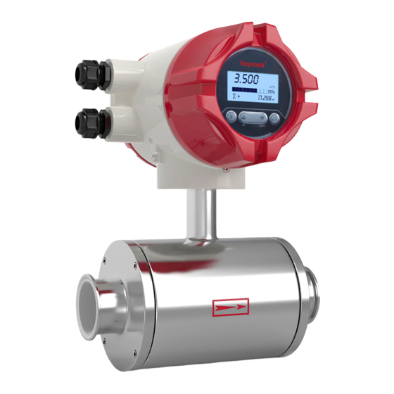
Otherwise, please contact manufacturer or supplier. (1) Remote type flowmeter Figure 1 Remote type flowmeter signal converter Remote type electromagnetic flowmeter sensor www.supmea.com... - Page 10 Chapter 2 Introduction Signal cable User manual (2) Compact type flowmeter (DN65, refer to type selection manual for specific parameters) Figure 2 Compact type electromagnetic flowmeter User manual www.supmea.com...
-
Page 11: Measuring Principle
The flow of conductive fluid induces a potential proportional to the average flow velocity, thus requiring the conductivity of the measured flowing liquid to be higher than the minimum conductivity (5us/cm). The induced voltage signal is detected by two electrodes and transmitted to the www.supmea.com... -
Page 12: Mechanical Construction
(4) Electrode: A pair of electrodes is installed on the wall of the measuring tube which is perpendicular to the magnetic line to detect the flow signal. The material of electrode can be selected according to the corrosion www.supmea.com... -
Page 13: Application Introduction
50μ S/cm. Meanwhile, the conductivity measured online must prevail, for that measured offline may be relatively higher due to carbon dioxide and nitrogen dioxide contained in the air may dissolve into the medium. www.supmea.com... -
Page 14: Wiring Introduction
Chapter 2 Introduction 2.5. Wiring introduction Remote type Figure 5 L, N: 100-240VAC power supply Ground ALM1,ALM2: Relay out POUT,PCOM: Pulse/Frequency output 485A,485B: RS485 communication IOUT,ICOM: 4-20mA output EXT1,EXT2: Excitation signal SIG1,SIG2,SGND: Electrode signal DS1,DS2: Electrode shield www.supmea.com... - Page 15 Chapter 2 Introduction Compact type Figure 6 L, N: 100-240VAC power supply 485A,485B: RS485 communication IOUT,ICOM: 4-20mA output connection POUT,PCOM: Pulse/Frequency/Relay out CCOM: RS485 communication ground Converter instrument grounding protection www.supmea.com -10-...
-
Page 16: Nameplate
Instead, you need to check whether the parameters indicated on the nameplate are correctly preset against with the actual working conditions. The following are parameters on the nameplate. Figure 7 It is strictly prohibited to open the cover with electricity www.supmea.com -11-... -
Page 17: Chapter 3 Installation
(1) Leave enough space on the side. (2) Do not make the electromagnetic flowmeter subject to violent vibration. 3.4. Pipe design (1) Location The electromagnetic flowmeter shall be installed in a dry and ventilated place. A place easy for water accumulation shall be avoided. www.supmea.com -12-... - Page 18 10 times of pipe diameters (10D), and the length of straight pipe on the downstream be at least 5 times of pipe diameters (5D) www.supmea.com -13-...
- Page 19 When the electromagnetic flowmeter is required to be installed underground, the pipes at both inlet and outlet ends shall be provided with support items, and a metal protection plate shall be installed above the flowmeter. ≥10D ≥5D Figure 8 ≥5D ≥ Figure 9 www.supmea.com -14-...
-
Page 20: Installation Conditions
Preferred produce measurement errors!) location It is easy to cause a non-full tube measurement error! Figure 11 (2) Installation direction of electromagnetic flowmeter and sensor electrodes The sensor allows horizontal and vertical installation. When it’s installed www.supmea.com -15-... - Page 21 In addition, impurities will not precipitate at the bottom of the measuring tube. It shall be guaranteed that liquids flow from bottom to top to ensure that the sensor measuring tube is always filled with medium. www.supmea.com -16-...
- Page 22 (6) For pipes with open discharges, the electromagnetic flowmeter shall be installed at the bottom section (lower part of the pipe). Figure 15 (7) For places where fall head of pipes is over 5 m, the air valve shall be installed on the downstream of the electromagnetic flowmeter. www.supmea.com -17-...
- Page 23 It’s not allowed to install the electromagnetic flowmeter at a place where the liquid conductivity is extremely uneven. Injection of chemicals from the upstream of the meter can easily result in uneven liquid conductivity, which can cause serious www.supmea.com -18-...
-
Page 24: Mechanical Installation
(2) In general, foreign matters (such as welding slag) may exist in newly installed pipelines. Before the flowmeter is installed, wash away the debris. It not only prevents the lining from being damaged but also measurement error caused by foreign matters which pass through the measuring tube during measurement. www.supmea.com -19-... -
Page 25: Precautions
Then cover terminal box and tighten the screws to ensure the tightness. If the protection level of the electromagnetic flowmeter is IP68 at type selection, it has been subject to water-proof sealing. www.supmea.com -20-... - Page 26 B. Conduct regular inspection. Check against the measures mentioned above and the terminal box for at least once a year. In the event of water entry into the meter (eg, after heavy rain, etc.), the meter shall be inspected immediately. www.supmea.com -21-...
-
Page 27: Installation Of Flowmeter
When the flowmeter is installed, the inner diameter of sealing washers shall be slightly larger than that of the pipe to aviod interference to the fluids in the pipe. Flange Nut Seal washer Bolt Figure 19 www.supmea.com -22-... -
Page 28: Dimensions For Electromagnetic Flowmeter
Chapter 3 Installation 3.7. Dimensions for electromagnetic flowmeter flowmeter(mm) Flange (mm) Pressure (Mpa) 4-φ7 4-φ14 4-φ14 4-φ14 4-φ14 4-φ18 4-φ18 4-φ18 8-φ18 8.φ18 8-φ18 8-φ18 8-φ23 8-φ23 12-φ23 12-φ23 www.supmea.com -23-... - Page 29 1220 1160 28-φ34 1200 1200 1585 1130 1405 1340 32-φ34 1400 1400 1810 1260 1630 1560 36-φ36 1600 1600 2040 1450 1830 1760 40-φ36 1800 1800 2250 1640 2045 1970 44-φ39 2000 2000 2460 1820 2265 2180 48-φ42 www.supmea.com -24-...
-
Page 30: Chapter 4 Electrical Connection
The equipment must be grounded in accordance with regulations so as to protect the operator from electrical shock. Danger! In case that equipment is used in explosion danger areas, special notes are given to explosion-proof instructions for safety tips. www.supmea.com -25-... - Page 31 Compact type (caliber: 65, refer to type selection manual for specific parameters) Figure 20 Connection description Excitation output: EXT1--Sensor excitation coil positive terminal EXT1--Sensor excitation coil negative terminal Signal output: SIG1-The positive electrode sensor signal SIG2--The negative electrode sensor signal SGND--Signal ground www.supmea.com -26-...
-
Page 32: Potential Equalization
(3) It is not allowed to connect other electrical equipment to the grounding conductor at the same time. 4.4. Power supply Danger! The equipment must be grounded in accordance with regulations so as to protect the operator from electrical shock. (1) 100-240VAC power supply Figure 21 www.supmea.com -27-... - Page 33 : Connect ground wire to the ground screw (2) 24VDC power supply Figure 22 Tips! Allowable range: 22VDC -26VDC 24+: 24VDC Power supply positive pole 24-: 24VDCPower supply negative pole : Connect ground wire to the ground screw. www.supmea.com -28-...
-
Page 34: Output Termination
485A, 485B: RS485 communication output CCOM: RS485 communication ground Protocol: ModBus-RTU Pulse, frequency output and relay out Pulse output: POUT, PCOM Relay out :ALM1,ALM2 Active mode: High 24V, 5mAdrive current Output electrical isolation: photoelectric isolation, isolation voltage: > 1000VDC www.supmea.com -29-... - Page 35 Additional remarks: pulse output is OC gate output, it needs external power supply. The general counters are equipped with pull-up resistors, and the signal can be directly connected therein. Manufacturer's suggestion: use a pull-up resistor R of 2K, 0.5W, and 24V DC power supply for power supply www.supmea.com -30-...
-
Page 36: Chapter 5 Start Up
All parameters and hardware are configured according to your order. After energization, the instrument will perform self-check for one time. Then it will immediately begin to measure and display the current values. Figure 25 Startup interface www.supmea.com -31-... -
Page 37: Chapter 6 Operation
Σ: Net flow accumulation, V: current flow rate, MT: Current conductivity] (7) Operation keys: mechanical / photoelectric keys Mark Measuring Menu mode Function mode Data mode mode > Switch menu Data right categories shift Switch Switch menu Confirmation Confirm accumulative subclass data ↲ amount www.supmea.com -32-... -
Page 38: Display (Operation Mode)
Except key combination, it is forbidden to put other fingers on the other photoelectric keys when operating the touch-key. Photoelectric keys are optional, please see type selection manual for details. Figure 27 www.supmea.com -33-... -
Page 39: Display Button Operation Instructions
Key parameters to facilitate the manufacturer and user to quickly set up the meter: Press on at the same time to enter the parameter setting interface. Enter the password. Quickly set the password: 300000(Used to modify the quick setup menu) www.supmea.com -34-... -
Page 40: Configuration Details
. When the flow unit is volume, this parameter are not displayed. Density unit : g/cm Time Figure User 0-99S constant Damping coefficient of the filter, select the average selected within the time parameter as the real-time flow. Flow Figure User 0-10% resection www.supmea.com -35-... - Page 41 The peak amplitude (not shown when peak inhibition allows configuration closing ) 1-10 Flow Option Manufacturer Y, N correction permission Indicates whether start using flow nonlinear correction function. In principle, used for small flow rate (less than 0.5 m/s) linear www.supmea.com -36-...
- Page 42 Note: when set the modified point, shall keep the following relationship Modified point 1 > Modified point 2 > Modified point 3 > Modified point 4 > 0 The intermediate value of correction coefficient is 1.0000, if the correction www.supmea.com -37-...
- Page 43 Flow rate modified point 3, when The flow rate function is disabled, this parameter does not display. 1-17 Flow Figure Manufacturer 0.0-99.999 correction coefficient 4 Flow rate modified point 4, when The flow rate function is disabled, this parameter does not display. 1-18 Flow Figure Manufacturer 0.0-99.999 1.000 www.supmea.com -38-...
- Page 44 User 0-5000 2000 frequency Set the corresponding frequency of the real-time flow upper limit ; When selecting frequency output, this parameter displays. Pulse value Option User 0.001-999.99 ( L/P) Set the cumulant that each pulse stands for ; www.supmea.com -39-...
- Page 45 Touch spot outputs high and low level under no alarm state . Alarm1 output Option User allowed Allow contact 1 output of main switch, when it’s set to be N, the following parameters do not display. Allow alarm1 Option User empty pipe www.supmea.com -40-...
- Page 46 Used to eliminate the alarm disturbance Upper limit elimination conditions: real-time flow is less than the upper limit alarm value minus return difference Lower limit elimination conditions: real-time flow is greater than the lower limit alarm value plus return difference www.supmea.com -41-...
- Page 47 EVEN Serial communication verification mode of physical layer 2-1 4-3、3-4 2-1 4-3 1-2、4-3 1-2、 Byte swap Option User 1-2 3-4 Byte exchange sequence of physical layer serial communication Device Figure User 0-999999 000001 address HART device identification number www.supmea.com -42-...
- Page 48 Measured conductivity equivalent value when the tube is full, default values can be used for general natural water. It needs to observe whether the empty pipe for special fluid is that displayed as 9-1, then record it in 9-4. Empty pipe Figure Manufacturer 0-9999 detection www.supmea.com -43-...
- Page 49 For correcting the sensor’s nonlinear correction for small flow (below 0.3 m/s) For details, see sensor coefficient calibration section. Excitation Option Manufacturer 3.125Hz 、 6.25Hz mode 6.25 Hz 、 12.5 10-7 Hz 、 25 Hz Selection of excitation frequency 3.125Hz 、6.25Hz、12.5Hz、25 Hz www.supmea.com -44-...
- Page 50 Source code Option Manufacturer After set to Y, the original code of the signal will be displayed on the 11-2 running screen, and this screen will display the firmware version number and product serial number at the same time www.supmea.com -45-...
-
Page 51: Brief Operating Instruction And Function
Users can conduct the switch operation in the menu by pressing and button, switch among the parameter item of menu by pressing the button and meanwhile store a modified parameter value. Adjust the parameter value by pressing button. Such as flow upper limit. Figure 29 www.supmea.com -46-... -
Page 52: Display Measurement
Chapter 6 Operation 6.6.2. Display measurement ∑+: Forward cummulant ,∑-: Reverse cummulant, Σ:Net cummulant, V: Current This picture will display after startup flow velocity,MT: Conductivity equivalent Figure 30 www.supmea.com -47-... -
Page 53: Flow Setup And Analog Output Menu
Chapter 6 Operation 6.6.3. Flow setup and analog output menu Figure 31 www.supmea.com -48-... -
Page 54: Pulse Output And Total Set Menu
Chapter 6 Operation 6.6.4. Pulse output and total set menu Figure 32 6.6.5. Relay out setup menu Figure 33 www.supmea.com -49-... -
Page 55: System Function, Empty Pipe Function, Sensor Function, Test Function Setup Menu
Chapter 6 Operation 6.6.6. System function, empty pipe function, sensor function, test function setup menu Figure 34 www.supmea.com -50-... -
Page 56: Chapter 7 Display Functions
Sensor signal is greater than the AD sampling of the upper limit AD_Hi The current real-time flow rate exceeds the setting flow limit The current real-time flow rate exceeds systemAD sampling limit Rng_Hi The range scope set by user exceeds the upper limit of pulse output. Pls_Hi www.supmea.com -51-... -
Page 57: Pulse/Frequency/Current Output
Pulse equivalent output is different from frequency output; pulse output will output a pulse when a pulse equivalent is accumulated enough, so the pulse output is uneven. Counter instrument should be used when measuring pulse output. Frequency meter instrument shouldn’t be used. www.supmea.com -52-... -
Page 58: Frequency Output
Indicate real-time flow rate real time Indicate current instrument range Indicate real-time current value real time 7.3. Communication This instrument provides a standard RS485 communication interface, using the international standard MODBUS-RTU communication protocol that supports 04 Read Holding Registers command. www.supmea.com -53-... -
Page 59: Registered Address
Reverse flow ulong The decimal part magnifies accumulation of by 1,000 times 123 stands decimal for 0.123 Note: Float/ulong/long type data, Communication transmission is in byte order2-1-4-3; ushort type data transmission is in accordance with 2-1. www.supmea.com -54-... -
Page 60: Communication Configuration
Forward flow rate accumulate readout Send message: 08 04 00 6B 00 04 80 8C Return message: 08 04 08 00 6C 00 00 00 7B 00 00 D6 8E (The cumulative integer: 108, Cumulative decimal: 0.123, Accumulation: 108.123) www.supmea.com -55-... -
Page 61: Chapter 8 Technical Parameters
(only IP68 protection of remote type sensor) Immersion depth Less than 3 meters (only IP68 protection of remote type sensor) Sensor cable Only for remote type, the standard 10m cable; other cables suggest custom no longer than 20 meters. www.supmea.com -56-... - Page 62 Operating Environment Temperature -10 ℃ - 55 ℃ for Compact-Type Flowmeter -10 ℃ - 60 ℃ for Converter of Remote-Type Flowmeter Environment -10 ℃ – 55 ℃ for Converter of Remote-Type Flowmeter Storage -40 ℃ - 65 ℃ -57- www.supmea.com...
- Page 63 Output pulse width: 0.25ms ~100ms Pulse output basis Duty cycle: 50% (Pulse frequency ≥5Hz) Fmax ≤ 5000 cp/s setting 0.001L – 1m frequency Fmax ≤ 5000Hz setting 0-5000Hz passive ≤ 36VDC Outer Status output function Output as alarm passive ≤ 36VDC Outer www.supmea.com -58-...
-
Page 64: Electrode Selection And Specification
So this table is only for reference. Users may make their ownchoices based on actual situation. You may refer to corrosion prevention manual for general media. But for media with complex compositions like mixed acid, you may need to conduct corrosion tests for materials to be selected. www.supmea.com -59-... -
Page 65: Flowmeter
1000-4000 5000-12216 139-1200 1600-5000 6000-16620 181-1600 2000-6000 8000-21720 229-1600 2000-8000 10000-27480 1000 283-2000 2500-10000 12000-33924 1200 407-2500 3000-12000 16000-48833 1400 554-3000 4000-16000 20000-66468 1600 723-4000 5000-20000 27000-86815 Reduction formula: (Flow )Q = (flow velocity) V×π×(DN/2) ,Unit: m/s and www.supmea.com -60-... -
Page 66: Flow And Velocity Parallel Table For Electromagnetic Flowmeter
27150 DN900 229.0 1145 2290 22902 27480 34350 DN1000 1131 1414 2827 28274 33924 42405 48832. DN1200 1628 2034.7 4069.4 40694 61041 DN1400 1108 2216 2769.5 5539.4 55390 66468 83085 86815. DN1600 1447 2894 3617.3 7234.6 72346 108519 www.supmea.com -61-... -
Page 67: Accuracy
Chapter 8 Technical parameters 8.5. Accuracy Reference condition (1) Medium: water (2) Temperature: 20℃ (3) Pressure: 0.1MPa (4) Front straight conduit: ≥5DN, Rear straight conduit: ≥2DN Figure 36 X[m/s]: Flow rate Y[%]: Actual measured value deviation(mV) www.supmea.com -62-... -
Page 68: Chapter 9 Plug-In Type Electromagnetic Flowmeter Series
The flowmeter is not limited to 0~10mA(DC) or 4~20mA (DC) standard current output and 1 ~ 5kHz frequency output at the same time. Because the flowmeter ( sensor ) has the above-mentioned advantages, it has www.supmea.com -63-... -
Page 69: Product Form And Composition
The highest temperature of the measured medium: ABS60℃ Shell protection level: It complies with the relevant provisions of IP68 of GB-08-84 standard. (10) Sensor output signal: 0.209mVp-p/1m/s. (11) The maximum transmission distance between the sensor and the converter is www.supmea.com -64-... -
Page 70: Structure
Faraday's law of electromagnetic induction. Terminal box: The junction box is located on the top of the sensor. The terminals in the junction box act as a connection between the sensor and the converter. www.supmea.com -65-... - Page 71 Sealing mechanism: composed of pressing screw seat, pressing nut, rubber washer and set screw made of stainless steel material. It is used to seal and insert the electromagnetic sensor so that it can withstand a certain working pressure. www.supmea.com -66-...
Need help?
Do you have a question about the SUP-LDG and is the answer not in the manual?
Questions and answers