Table of Contents
Advertisement
Quick Links
Advertisement
Table of Contents

Related Manuals for SUPMEA SUP-1158S


Summary of Contents for SUPMEA SUP-1158S
- Page 1 Ultrasonic Flow Meter User Manual SUP-1158S...
-
Page 2: Table Of Contents
SUP-1158S User Manual Contents 1. Introduction............................ 4 1.1 Preface..........................4 1.2 Features..........................4 1.3 Flow measurement principle....................4 1.4 Optional transducer......................5 1.5 Typical application......................5 1.6 Product Identification......................5 1.7 SUPcifications........................5 2. Installation and Measurement......................7 2.1 Wiring diagram........................7 2.2 Keypad..........................7 2.3 Menu Windows........................8... -
Page 3: Sup-1158S User Manual
SUP-1158S User Manual 4.4 How to select a required flow rate unit................27 4.5 How to use the totalizer multiplier.................. 27 4.6 How to open or shut the totalizers................... 27 4.7 How to reset the totalizers....................27 4.8 How to restore the flow meter with default setups............27 4.9 How to use the damper..................... -
Page 4: Introduction
◆ 1.3 Flow measurement principle The SUP-1158S ultrasonic flow meter is designed to measure the fluid velocity of liquid within a closed conduit. The transducers are a non-contacting, clamp-on type, which will provide benefits of non- fouling operation and easy installation. -
Page 5: Optional Transducer
SUP-1158S User Manual Where θ is the include angle to the flow direction M is the travel times of the ultrasonic beam D is the pipe diameter Tup is the time for the beam from upstream transducer to the downstream one Tdown is the time for the beam from downstream transducer to the upstream one ΔT=Tup –Tdown... -
Page 6: Supcifications
SUP-1158S User Manual 1.7 SUPcifications Items SUPcification Accuracy Better than ±1% Repeatability Better than 0.2% Principle Transit-time measuring principle Measurement 500ms Period LCD with backlight, display accumulated flow/heat, instantaneous Main unit Display flow/heat, velocity, time etc. Analogue output: 4-20mA or 0-20mA current output. Impedance 0∼... -
Page 7: Installation And Measurement
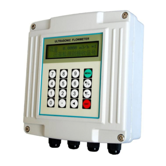
SUP-1158S User Manual 2. Installation and Measurement 2.1 Wiring diagram 2.2 Keypad The keypad for the operation of the flow meter is as shown by the right picture. Keys are keys to enter numbers ▲/+ is the going UP key, when the user wants to go to the upper menu window. -
Page 8: Menu Windows
SUP-1158S User Manual ◄ is backspace key, when the user wants go left or wants backspace the left character that is located to the left of the cursor. ENT is the ENTER key for any inputting or selections. is the key for the direct menu window jump over. Whenever the user wants to proceed to a MENU certain menu window, the user can press this key followed by 2-digit numbers. -
Page 9: Steps To Configure The Parameters
SUP-1158S User Manual message is indicated on the lowest line of the LCD display, it means the modification operations is locked out. In such cases, the user should go to M47 to have the instrument unlocked first before any further modification can be made. -
Page 10: Transducers Mounting Allocation
SUP-1158S User Manual MENU (11) Press to check up signal strength and quality, the bigger of the value the better. Generally the signal strength should be better than 60.0, and signal quality should be better than 50.0. to check up time ratio, the ratio value should be in the range of 100±3%... -
Page 11: Transducers Installation
SUP-1158S User Manual Examples of optimum locations. Principles to selection of an optimum location (1) Install the transducers on a longer length of the straight pipe. The longer the better, and make sure that the pipe is completely full of liquid. -
Page 12: Wiring Diagram Of Transducer
SUP-1158S User Manual 2.6.1 Wiring diagram of transducer 2.6.2 Transducers Spacing The spacing value shown on menu window M25 refers to the distance of inner spacing between the two transducers. The actual transducers spacing should be as close as possible to the spacing value. -
Page 13: Z-Method Installation
SUP-1158S User Manual 2.6.4 Z-method Installation Z-method is commonly used when the pipe diameter is above 200mm. 2.6.5 W-method Installation W-method is usually used on pipes with a diameter from 15mm to 50mm. -
Page 14: N-Method Installation
User Manual SUP-1158S 2.6.6 N-method Installation Rarely used method. 2.7 Installation Checkup Through the checkup of the installation, one can: check the receiving signal strength, the signal quality Q value, the traveling time difference of the signals, the estimated liquid SUPed, the measured traveling time of the signals and the calculated traveling time ratio. -
Page 15: Signal Quality
User Manual SUP-1158S 2.7.2 Signal quality Signal quality is indicated as the Q value in the instrument. A higher Q value would mean a higher Signal and Noise Ratio (short for SNR), and accordingly a higher degree of accuracy would be achieved. -
Page 16: Menu Window Details
User Manual SUP-1158S M60-M78 windows for time-keeper initialization, version and ESN information viewing and alarms. window for viewing date totalizer. M90~M94 are diagnostic windows for a more accurate measurement. M97~M99 are not windows but commands for the outputting of display copying and pipe parameter setups. - Page 17 User Manual SUP-1158S Note: you just need to enter either the outer diameter in M11 or the peripheral in M10 Window for entering pipe wall thickness You may skip the menu and enter inner diameter in M13 instead. Window for entering the inner diameter of the pipe...
- Page 18 User Manual SUP-1158S Standard-HM (middle size transducer for Handheld flow meter) 10. Standard-M1 (middle size transducer #1) 11. Standard-S1 (small size transducer #1) 12. Standard-L1 (large size transducer #1) 13. PI-Type 14. FS410 (middle size transducer for FUJI flow meter) 15.
- Page 19 User Manual SUP-1158S Flow rate can be in 0. Cubic meter short for 1. Liter 2. USA gallon (gal) 3. Imperial Gallon (igl) 4. Million USA gallon (mgl) 5. Cubic feet (cf) 6. USA liquid barrel (bal) 7. Oil barrel (ob) The flow unit in terms of time can be per day, per hour, per minute or per second.
- Page 20 User Manual SUP-1158S Entry to linearity correcting data inputs. By using of this function, the non-linearity of flow meter will be corrected. Correcting data shall be obtained by careful calibration. Displays the input contents for the serial port. By checking the displays, you can know if the communication is ok.
- Page 21 User Manual SUP-1158S The following parameters can be configured: Baud rate (300 to 19200 bps), parity, data bits (always is 8), stop bits (1). Select communication protocol. Factory default is ‘MODBUS ASCII. this is a mode for MODBUS-ASCII, Meter-BUS, Fuji Extended Protocol, Huizhong’s various protocols.
- Page 22 User Manual SUP-1158S 2. Not Ready (No*R) 3. Reverse Flow 4. AO Over 100% 5. FO Over 120% 6. Alarm #1 7. Reverse Alarm #2 8. Batch Control 9. POS Int Pulse 10.NEG Int Pulse 11.NET Int Pulse 12.Energy POS Pulse 13.Energy NEG Pulse...
- Page 23 User Manual SUP-1158S sources: 0. Key input (press ENT key to start the batch controller) 1. Serial port 2. AI3 rising edge (when AI3 receives 2mA or more current) 3. AI3 falling edge (when AI3 stop receiving 2mA or more current) 4.
- Page 24 User Manual SUP-1158S from AI3,AI4 Select the SUPcific Heat Value. Factory default is ‘GB’. Under this setting, the flow meter will calculate the enthalpy of water based on the international standard. If the fluid is other than water, you should select option ‘1. Fixed SUPcific Heat’, and enter the SUPcific heat value of the fluid.
- Page 25 User Manual SUP-1158S This is not a window but a command to copy the current display window. By default, the produced data will be directed to the internal serial bus (thermal printer). You can also direct those data to the serial communication port.
-
Page 26: How To
SUP-1158S User Manual Note: 1. Windows in are new to our older version of flow meter 2. Windows in blue are energy related windows 3. The term totalizer is also called accumulator 4. How To 4.1 How to judge if the instrument works properly Enter into M08, if ‘R’... -
Page 27: How To Select A Required Flow Rate Unit
SUP-1158S User Manual 4.4 How to select a required flow rate unit Use menu window M31 to select the flow unit first and then the timing unit. 4.5 How to use the totalizer multiplier Use window M33 to select a proper totalizer. Make sure that the totalizer pulse is appropriately SUPeded. -
Page 28: How To Use The Zero-Cutoff Function
SUP-1158S User Manual 4.10 How to use the zero-cutoff function The number displayed in window M41 is called the lower flow rate cut-off value. The flow meter will replace these flow rate values that are absolutely less than the low-cutoff value with ‘0’. This means the flow meter will avoid any invalid accumulation when the actual flow is below the zero-cutoff value. -
Page 29: How To Use The Frequency Output
SUP-1158S User Manual such as 4-20mA mode, 0-20mA etc. Mode selection can be made in menu M55. Refer to the next chapter for details on M55. In order to use the 4-20mA output function, you need not only select the mode to be 4-20mA in M55, but also set the flow rate values which correspond to the minimum current (4mA) and the maximum current (20mA). -
Page 30: How To Use The Totalizer Pulse Output
SUP-1158S User Manual instrumentation. The user should enter 0 in M68 and 3000 in M69, and enter 200 and 1000 in window M67. Please note that the user has to make the selection with OCT setups in window M78. 4.16 How to use the Totalizer Pulse Output The totalizer output will produce a pulse output with every unit flow of the totalizer. -
Page 31: How To Use The Built-In Buzzer
SUP-1158S User Manual (2) Enter flow rate upper limit 1000 in M74 for #1 alarm, (3) Select item '6. Alarm #1' in M77. Example C: assume we need the OCT output to activate when flow rate exceeds 100~500m /h and the relay output to activate when flow rate exceeds 600~1000m3/h. -
Page 32: How To Use The Working Timer
4.25 How to check the ESN and other minor details Every set of the SUP-1158S flow meter utilizes a unique ESN to identify the meter. The ESN is an 8- digit number that provides the information of version and manufacturing date. -
Page 33: How To Adjust The Lcd Display
SUP-1158S User Manual 4.28 How to adjust the LCD display You may use menu window 70 to setup the LCD display backlight and menu window 71to adjust contrast it. 4.29 How to use RS232/RS485? Use menu window 62 to set up RS232/RS485. All the devices connected with flow meter should have matched serial configuration. -
Page 34: How To Solidify The Parameters
SUP-1158S User Manual 4.33 How to solidify the parameters There are three kinds of parameters for the new generation SUP-1158: 1) Current parameters, the parameters are stored in the RAM. They will be lost when one cut the power or remove the reserve battery. -
Page 35: How To Save / Restore Frequently-Used Pipe Parameters
SUP-1158S User Manual 50.56 51.23 0.99 In order to revised the flow exceed the scope of the above table, without mutations of correction factor, we add two points on the basis of the above five points, (0 m /h, 1.0) and (100000 m /h, 1.0). -
Page 36: Troubleshooting
5.2 Error Code and Counter-Measures The SUP-1158S ultrasonic flow meter will show Error Code in the lower right corner with a single letter like I, R etc. on menu windows M00, M01, M02, M03, M90 and M08. When any abnormal Error Code shows, counter-measures should be taken. -
Page 37: Other Problems And Solutions
SUP-1158S User Manual (5)Problem with transducers coupler cords Check value The actual frequency for the entered M66, Frequ Output Over Frequency Output is out of the M67,M68 and M69, range set by the user and try to enter a larger value on M69...
Need help?
Do you have a question about the SUP-1158S and is the answer not in the manual?
Questions and answers