Advertisement
Quick Links
Advertisement

Subscribe to Our Youtube Channel
Related Manuals for SpeedyBee Master 5 V2

Summary of Contents for SpeedyBee Master 5 V2
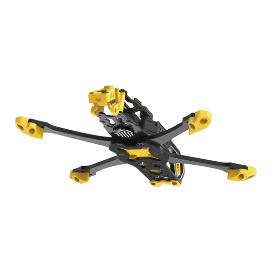
- Page 1 * (Note: 3D e昀昀ect requirements, the actual object shall prevail)
- Page 2 CNC camera mount and camera side plate installation M3*5 Front top plate Install the front top plate M2*3 Camera side plate Antenna Installation Sequence inse爀琀 the O-ring into the antenna to secure it on the TPU antenna base.
- Page 3 Install the multi-function antenna base Choose a suitable VTX antenna base (*Note: pictures for assembly reference only. Frame doesn’t include antenna) SMA antenna base M2.5*8 Choose a suitable VTX antenna base Install the plate on one side and GPS base Install the T-shaped antenna M3*23 stando昀昀...
- Page 4 *Notice: front and back arms Install arms and anti-vibration module (Complete the installation of 4 arms in turn) Front arm Back arm Screws pass through the bottom plate and the intersection position of the arms in turn Direction for drone head Install the anti-vibration stack module to the corresponding position M3*14...
- Page 5 Install middle plate Install the middle plate to the corresponding 6 screw positions middle plate Place for capacitor and buzzer bottom plate Tighten the two press-in nuts where the arms intersect M2*8...
- Page 6 Combination with completed pa爀琀s 1 and 2 Install 7075 stando昀昀 Combination of frame and CNC camera mount M3*5 M3*6 M2.5*6 Bottom protection silicone (0.5mm) Frame and antenna base combination...
- Page 7 Install rear top plate and batte爀礀 anti-slip silicone M3*6 Batte爀礀 anti-slip silicone (2.5mm) Rear top plate M3*6 Stack protector M2*4 M3*6 Finally, install the rear top plate and batte爀礀 anti-slip silicone *Notice: please change to M3*6 button head hex socket screws if installing TPU protection at the drone head pa爀琀.
- Page 8 Arm foot mount installation Install the 3D printed foot mount to arms Use screw of proper length based on the motor installation M3*10 M3*8 (*Notice: default screws are M3*8mm, M3*10mm)
- Page 9 O3 Air Unit Installation Method Pass through the top of the VTX O3 Air Unit 6P 昀氀ex cable O3 Air Unit VTX Master honeycomb heat sink M1.6*8 The 4 original screws at the bottom of the O3 Air Unit need to be removed...
- Page 10 Recommend installing ESC in reverse horizontally 180° *Note (After the ESC is installed reversely, remember to rede昀椀ne the correct position and direction of motors 1-4.) It is recommended to keep the power cable of ESC to be about 100mm. Please refer to the used batte爀礀 for actual length. Suggesting place for main power cable...
- Page 11 ESC power cable soldering and recommended length for cable of motor *Note: connect buzzer with mark to BZ+ of 昀氀ight controller, and buzzer without mark to BZ- Capacitor Buzzer Inner motor wire recommended Outer motor wire recommended length: 110mm length: 93mm 外走线推荐电机线长为93mm 1�1 Scale 100 110 120 130 140...
- Page 12 Scan the QR code to get the installation guide. We recommend you scan it through the SpeedyBee App for detailed instructions. SpeedyBee APP Installation Guidance Facebook QR Code...
Need help?
Do you have a question about the Master 5 V2 and is the answer not in the manual?
Questions and answers