
Subscribe to Our Youtube Channel
Related Manuals for Comelit IPLPRA02ZA


Summary of Contents for Comelit IPLPRA02ZA
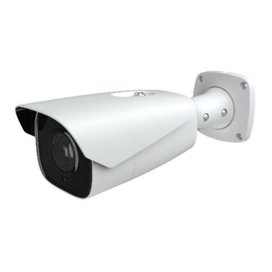
- Page 1 IP LPR CAMERA ART. IPLPRA02ZA Please read this manual thoroughly before use and keep it for future reference...
- Page 2 WARNING This product is intended to be supplied by a Listed Power Unit, marked with 'Limited Power Source', 'LPS' on unit, output rated minimum 12VDC/2 A or POE 48VDC/ 350mA or 24VAC (depending on models), no more than 2000m altitude of operation and Tma= 60°C.
-
Page 3: Table Of Contents
Table of Contents Network Connection ..................1 LAN ......................1 1.1.1 Access through Comelit Advance IP Tool ........1 1.1.2 Access through Internet Explorer ........... 3 WAN ......................4 Live View ......................8 Network Camera Configuration ..............10 System Configuration ................10 3.1.1... - Page 4 3.5.11 HTTPS ..................41 3.5.12 P2P (optional)................42 3.5.13 QoS ....................43 Security Configuration ................43 3.6.1 User Configuration ............... 43 3.6.2 Online User .................. 44 3.6.3 Block and Allow Lists ..............45 3.6.4 Security Management ..............45 Maintenance Configuration ............... 46 3.7.1 Backup and Restore ..............
-
Page 5: Network Connection
1.1.1 Access through Comelit Advance IP Tool Network connection: ① Make sure the PC and IPC are connected to the LAN and the Comelit Advance IP Tool is installed in the PC. ② Double click the Comelit Advance IP Tool icon on the desktop to run this software as shown below: ③... - Page 6 For example, the IP address of your computer is 192.168.1.4. Therefore, the IP address of the camera shall be changed to 192.168.1.X. After modification, please enter the password of the administrator and click the “Modify” button to modify the setting. ...
-
Page 7: Access Through Internet Explorer
The system will pop up the above textbox to ask you to change the default password. It is strongly recommended to change the default password for account security. If “Do not show again” is checked, the textbox will not appear the next time. 1.1.2 Access through Internet Explorer The default network settings are shown below: IP address: 192.168.1.150... -
Page 8: Wan
Select “Properties” and then select internet protocol (for example: IPv4). Next, click the “Properties” button to set the network of the PC. ② Open the Internet Explorer browser, enter the default address of the IPC and confirm. ③ Follow instructions to download and install the ActiveX control. ④... - Page 9 ① Make sure the camera is connected to the local network and then log in the camera via LAN and go to ConfigNetworkPort menu to set the port number. Port Setup ② Go to Config NetworkTCP/IP menu to modify the IP address. IP Setup ③...
- Page 10 Router Setup ④ Open the Internet Explorer browser and enter its WAN IP and http port to access. (for example, if the http port is changed to 81, please enter “192.198.1.150:81” in the address bar of web browser to access). ...
- Page 11 Access through static IP Network connection The setup steps are as follow: ① Go to ConfigNetworkPort menu to set the port number. ② Go to Config NetworkTCP/IP menu to set the IP address. Check “Use the following IP address” and then enter the static IP address and other parameters. ③...
-
Page 12: Live View
2 Live View After logging in, the following window will be shown. The following table is the instructions of the icons on the live view interface. Icon Description Icon Description Original size Zoom out Fit correct scale Zoom/Focus control Auto (fill the window) SD card recording indicator Full screen Sensor alarm indicator... - Page 13 Those smart alarm indicators will flash only if the camera supports those functions and the corresponding events are enabled. In full screen mode, double click with the mouse to exit or press the ESC key on the keyboard. Click AZ control button to show AZ control panel. The descriptions of the control panel are as follows: Icon Description...
-
Page 14: Network Camera Configuration
3 Network Camera Configuration In the Webcam client, choose “Config” to go to the configuration interface. Note: wherever applicable, click the “Save” button to save the settings. 3.1 System Configuration 3.1.1 Basic Information In the “Basic Information” interface, the system information of the device is listed. Some versions may support device ID and QR code. -
Page 15: Local Configuration
Select the time zone and DST as required. Click the “Date and Time” tab to set the time mode. 3.1.3 Local Configuration Go to Config System Local Config to set up the storage path of captured pictures and recorded videos on the local PC. There is also an option to enable or disable the bitrate display in the recorded files. - Page 16 Micro-SD Card Management Click the “Format” button to format the micro-SD card. All data will be erased by clicking this button. Click the “Eject” button to stop writing data to micro-SD card. Then the micro-SD card can be removed safely. Snapshot Quota: set the capacity of captured pictures on the micro-SD card.
- Page 17 Weekly schedule Set the alarm record time from Monday to Sunday for a single week. Each day is divided in one hour. Green means scheduled. Blank means unscheduled. “Add”: add the schedule for a specific day. Drag the mouse to set the time on the timeline.
-
Page 18: Image Configuration
Set the format, resolution and quality of the image saved on the micro-SD card, the snapshot interval and quantity and the timing snapshot here. Snapshot Quantity: is the maximum quantity of snapshots. The actual quantity of snapshots may be less than this number. Supposing the occurrence time of an alarm event is less than the time of capturing pictures, the actual quantity of snapshots is less than the set quantity of snapshots. - Page 19 Brightness: set the brightness level. Contrast: set the contrast. Hue: set the hue. Saturation: set the saturation. Sharpness: set the sharpness. Noise Reduction: decrease the noise to make the image more thorough. Increasing the value will make the noise reduction effect better but it will reduce the image resolution.
- Page 20 BLC: If enabled, the auto exposure will activate according to the scene so that the object of the image in the darkest area will be seen clearly. HFR: High Frame Rate. If “ON” is selected, the system will restart and then the maximum value of the frame rate of the main stream can be set to 60 fps /50fps.
-
Page 21: Video / Audio Configuration
configuration mode will automatically switch between day and night according to the schedule. 3.2.2 Video / Audio Configuration Go to Image Video / Audio interface as shown below. In this interface, set the resolution, frame rate, bitrate type, video quality and so on. Click the “Audio”... -
Page 22: Osd Configuration
Send Snapshot: set how many snapshots to generate for an event. Video encode slice split: if this function is enabled, smooth image can be gotten even though using the low-performance PC. Watermark: when playing back the local recorded video in the search interface, the watermark can be displayed. -
Page 23: Video Mask
3.2.4 Video Mask Go to Image Video Mask interface as shown below. A maximum of 4 zones can be setup. To set up video mask. 1. Enable video mask. 2. Click the “Draw Area” button and then drag the mouse to draw the area. 3. -
Page 24: Lens Control
1. Check “Enable” and then click the “Draw Area” button. 2. Drag the mouse to set the ROI area. 3. Set the level. 4. Click the “Save” button to save the settings. 3.2.6 Lens Control This function is only available for the model with motorized zoom lens. In this section, zoom and focus can be controlled. -
Page 25: Alarm Configuration
3.3 Alarm Configuration 3.3.1 Motion Detection Go to Alarm Motion Detection to set motion detection alarm. -
Page 26: Other Alarms
1. Check “Enable” check box to activate the function. Alarm Out: if selected, this would trigger an external relay output that is connected to the camera on detecting a motion based alarm Trigger Snap: if selected, the system will capture images on motion detection and save the images on the micro-SD card. - Page 27 2. Click “Enable” and set the Alarm Holding Time. 3. Set alarm trigger options. The setup steps are the same as motion detection. Please refer to motion detection chapter for details. Micro-SD card error When there are some errors in writing the micro-SD card, the corresponding alarms will be triggered.
-
Page 28: Alarm In
2. Click “Enable” and set the Alarm Holding Time. 3. Trigger Alarm Out. When the IP address of the camera is in conflict with the IP address of other devices, the system will trigger the alarm out. Cable disconnected ... -
Page 29: Alarm Out
1. Click “Enable” and set the alarm type, alarm holding time and sensor name. 2. Set alarm trigger options. The setup steps are the same as motion detection. 3. Click “Save” button to save the settings. 4. Set the schedule of the sensor alarm. The setup steps of the schedule are the same as the schedule recording setup. -
Page 30: Alarm Server
- Day/Night Switch Linkage: after selecting this mode, set the Alarm Type and then choose to Open or Close the alarm output when the camera switches to day mode or night mode. - Timing: select the alarm type. Select “Add” and drag the mouse on the timeline to set the schedule of alarm out. -
Page 31: Event Configuration
3.4 Event Configuration For more accuracy, here there are some recommendations for installation. Camera should be installed on stable surface, the vibrations can affect the accuracy of detection. Avoid pointing the camera at the reflective surfaces (like shiny floors, mirrors, glass, lake surfaces and so on). -
Page 32: Anpr
3. Click “Save” button to save the settings. 4. Set the sensitivity of the exception detection. Click “Sensitivity” tab to go to the interface as shown below. Drag the slider to set the sensitivity value or directly enter the sensitivity value in the textbox. - Page 33 Detection area Click “Draw Area” and drag the border lines of the rectangle to modify its size. Click “Stop Draw” to stop drawing the area. Click “Clear” to clear the area. Set the detectable size by defining the maximum value and the minimum value (the default size range of a single number plate image occupies from 5% to 50% of the entire image).
- Page 34 Add vehicles Click “Add” to show a vehicle adding box as shown in the above figure. Enter the license plate number, select list type, start and end time, enter owner and license plate type. Click “Save” to save the vehicle. List type: unknown vehicle, allow list or block list.
- Page 35 Set the fault tolerance, alarm list and check “alarm out”. Click “Save” to save all the settings. Fault tolerance. Up to 2 characters are allowed. For example, if “2” is selected, the captured license plate will be matched successfully and trigger the corresponding alarm even if there are 2 characters (or less) of the captured license plate not matched with the license plate of the alarm list.
- Page 36 ※ Camera configuration and surrounding area The monitoring image must cover the lane, entering/exiting vehicles and the plate number shall be always seen in the video. Avoid that the objects will block the camera image (as pillars, obstacles, doors, etc).
- Page 37 The tilt angle of the camera must be from 10° to 15°. If the camera is installed on the side of the road, the pan angle of the camera must be from 0° to 20°. If the camera is installed right above the middle of the road, the pan angle of the camera must be from -10°...
-
Page 38: Network Configuration
3.5 Network Configuration 3.5.1 TCP/IP Go to Config Network TCP/IP interface as shown below. Use IP address (IPv4 for example). There are two options for IP setup: "Obtain an IP address automatically" (by DHCP) and "Use the following IP address". Test: test the effectiveness of the IP address by clicking the button. -
Page 39: Port
This function is used for connecting the Comelit Advance VMS. 1. Check “Enable”. 2. Check the IP address and port of the transfer media server in the Comelit Advance VMS. Then enable the auto report in the Comelit Advance VMS when adding a new device. -
Page 40: Snmp
2. Apply for a domain name. Take www.comelitdns.com for example. Enter www.comelitdns.com in the IE address bar to visit its website. Choose your language and then click the “Register product” button. 3.5.5 SNMP To get camera status, parameters and alarm information and remotely manage the camera, the SNMP function can be used. -
Page 41: 802.1X
2. Check the corresponding version checkbox (Enable SNMPv1, Enable SNMPv2, Enable SNMPv3) according to the version of the SNMP software that will be used. 3. Set the values for “Read SNMP Community”, “Write SNMP Community”, “Trap Address”, “Trap Port” and so on. Please make sure the settings are the same as that of the SNMP software. -
Page 42: Rtsp
To use this function, the camera shall be connected to a switch supporting 802.1x protocol. The switch can be reckoned as an authentication system to identify the device in a local network. If the camera connected to the network interface of the switch has passed the authentication of the switch, it can be accessed via the local network. -
Page 43: Upnp
Audio: by entering the main/sub stream address in the VLC player, the video and audio will play automatically. If “Allow anonymous login…” is checked, there is no need to enter the username and password to view the video. If “auto start” is enabled, the multicast received data should be added into a VLC player to play the video. -
Page 44: Ftp
Sender Address: sender’s e-mail address. Username and Password: sender’s username and password. Server Address: SMTP IP address or hostname. Select the secure connection type at the “Secure Connection” pull-down list according to what’s required. SMTP Port: SMTP port. Send Interval(S): time interval of sending email. For example, if it is set to 60 seconds and multiple motion detection alarms are triggered within 60 seconds, they will be considered as only one alarm event and only one email will be sent. -
Page 45: Https
Server Name: name of the FTP server. Server Address: IP address or domain name of the FTP server. Upload Path: directory where files will be uploaded. Port: port of the FTP server. Use Name and Password: Username and Password that are used to login into the FTP server. -
Page 46: P2P (Optional)
3.5.12 P2P (optional) If this function is enabled, the network camera can be quickly accessed by adding the device ID in mobile surveillance client or Comelit Advance VMS client via WAN. ... -
Page 47: Qos
3.5.13 QoS QoS (Quality of Service) function is used to provide different quality of services for different network applications. With insufficient bandwidth, the router or switch will sort the data streams and transfer them according to their priority to solve the network delay and network congestion by using this function. -
Page 48: Online User
5. Enter the MAC address of the PC in “Bind MAC” textbox. If this option is enabled, only the PC with the specified MAC address can access the camera for that user. 6. Click the “OK” button and then the new added user will be displayed in the user list. Modify user: 1. -
Page 49: Block And Allow Lists
3.6.3 Block and Allow Lists Go to Config Security Block and Allow Lists as shown below. The setup steps are as follows: Check the “Enable address filtering” check box. Select “Block/Allow the following address”, IPv4/IPv6/MAC and then enter IP address or MAC address in the address box and click the “Add”... -
Page 50: Maintenance Configuration
Please set the password level and expiration time. Password Level: Weak, Medium or Strong. Weak level. Numbers, special characters, upper or lower case letters can be used. You can choose one of them or any combination of them when setting the password. Medium Level. -
Page 51: Reboot
3.7.2 Reboot Go to Config Maintenance Reboot. Click the “Reboot” button to reboot the device. Timed Reboot setting If necessary, the camera can be set up to reboot on a time interval. Enable “Time Settings”, set the date and time and then click the “Save” button to save the settings. 3.7.3 Upgrade ... -
Page 52: Search
4 Search 4.1 Image Search Click Search to go to the interface as shown below. The images saved on the micro-SD card can be found here. Local Image Search Choose “Picture”—“Local”. Set time: select the date and choose the start and end time. Click to search the images. - Page 53 Micro-SD card image search Choose “Picture”—“SD Card”. Set time: select the date and choose the start and end time. Choose the alarm events at the bottom of the interface. Click to search the images. Double click on the file name in the list to view the snapshots. ...
-
Page 54: Video Search
4.2 Video Search 4.2.1 Local Video Search Click Search to go to the interface as shown below. Videos were recorded locally to the PC can be played in this interface. Choose “Record”—“Local”. Set search time: select the date and choose the start and end time. Click to search the images. -
Page 55: Micro-Sd Card Video Search
Icon Description Icon Description Play button. After pausing the video, click Pause button this button to continue playing. Stop button Speed down Speed up Watermark display Enable / disable audio; drag the slider to adjust the volume after enabling audio. 4.2.2 Micro-SD card video search Click Search to go to the interface as shown below. - Page 56 The timetable can be shown in 24h/12h/2h/1h format by clicking the corresponding buttons. Video clip and downloading operations: Search the video files according to the above mentioned steps. Select the start time by clicking on the timetable. Click to set the start time and then this button turns green ( Select the end time by clicking on the timetable.
-
Page 57: Appendix
C: Web port number has been changed: contact administrator to get the correct port number. D: Exclude the above reasons. Restore to default setting by Comelit Advance IP Tool. Comelit Advance IP tool cannot search devices. The anti-virus software in your computer may cause it. Please stop it and try to search device again. - Page 58 No sound can be heard. A:Audio input device is not connected. Please connect and try again. B: Audio function is not enabled at the corresponding channel. Please enable this function.
Need help?
Do you have a question about the IPLPRA02ZA and is the answer not in the manual?
Questions and answers