
Related Manuals for Zepro 78826TL


Summary of Contents for Zepro 78826TL
- Page 1 OWNER'S MANUAL INFORMATION FOR OWNERS AND USERS Tail lift SLIDER LIFT 78826TL - Owner's Manual, English translation 2023-08-08 Must be kept in the vehicle on which the tail lift is installed...
-
Page 3: Table Of Contents
Contents Important information ................5 Technical support ..................5 Location of the type plate ................5 Spare parts & accessories ................. 6 Service ......................6 Product discontinuation ................6 Warranty...................... 6 REACH regulation ..................10 Information concerning the clause on remote diagnostics ....10 Privacy ...................... - Page 4 Loading and unloading with the platform on a loading dock .....35 Moving load from one vehicle to another ..........37 Wheel stop (accessory) ................38 Before use ....................42 4.10 After use ....................42 4.11 Autotilt (Option) ..................43 4.12 Fixed controller (CD20) ................45 4.13 Operating with the fixed control device (CD3)........49 4.14 Operating with the coiled cable control device (CD9) ......53...
-
Page 5: Important Information
Important information Important information Before using the ZEPRO tail lift, you must read and understand the contents of this manual and especially the sections describing safety. The owner’s manual is primarily intended to inform you about the tail lift’s functions and characteristics and how to use it in the best way. -
Page 6: Spare Parts & Accessories
Important information Spare parts & accessories If spare parts or accessories are required, contact your nearest service workshop. Service If service is required, contact your nearest service workshop. Product discontinuation For information on product discontinuation, see section ”9 Product discontinuation” on page 77. - Page 7 94. • The annual service was carried out according to ZEPRO’s instructions and by a ZEPRO-approved service workshop. Service must be noted in the service record. See section ”10 Service record” on page 79. •...
- Page 8 • External equipment: Damage caused by external equipment or materials not approved by ZEPRO. For ex- ample, equipment connected to the tail lift electrical system. Parts that have previous- ly been repaired without Z-lyften’s consent. •...
- Page 9 Important information • External costs: Emergency actions, on-call, travel expenses, vehicle hire, lost income, damage to goods. • Missing parts: If multiple parts are submitted with a claim application, parts that have no identified defects covered by the warranty will not be replaced. Example: An electrical hose rup- ture valve is found to be faulty and the valve and solenoid are both submitted; howe- ver, only the part that has a defect covered by the warranty will be replaced.
-
Page 10: Reach Regulation
Information concerning the clause on remote diagnostics ZEPRO, or a third party designated by ZEPRO, shall at all times have the right to (i) install, maintain and dismantle a remote diagnostics device in and from the Products; and (ii) -
Page 11: Privacy
Seller, and ZEPRO Group as the manufacturer of the Products, is required to collect and pro- cess information regarding the Customer, which may include personal data of the contact persons and other possible representatives and employees of the Customer. -
Page 12: Attention
Important information 1.11 Attention! The Instructions for use contain the following warning signs. They are intended to alert you to conditions that could cause problems, incidents, injury, and/or damage to the product, etc. WARNING! WARNING indicates a potential hazard, which if ignored may lead to serious, fatal injury. CAUTION! CAUTION indicates a potential hazard, which if ignored, may lead to minor injuries. -
Page 13: Safety Rules
NOTE! ZEPRO is not liable for any injury to persons or damage to property that may result from failure of the operator or other person to comply with the recommendations, warnings and instruc- tions set forth in these instructions for use. -
Page 14: Max Load
Safety rules Max load Under no circumstances may the lift be burdened with more weight than the specified maximum load. Under no circumstances may the max load centre be placed further out on the platform than the load centre distance specified for the tail lift. Information about the max permissible platform load and the load centre distance for max load is shown on stickers affixed to the tail lift or vehicle. WARNING! Under no circumstances is it permitted to load the platform with loads greater than those spe- cified on the stickers. Excessive load can cause structural damage. Risk of material damage and life-threatening injury. -
Page 15: Maintenance, Repairs And Service
When working on the tail lift, switch off the main power supply. Use only spare parts and accessories approved or recommended by ZEPRO. Any other use may lead to changes that impair tail lift function and safety. This may also render your tail lift warranty invalid. -
Page 16: Operation
Risk of material damage and life-threatening injury. CAUTION! ZEPRO is not liable for any injury to persons or damage to property that may result from failure of the operator or other person to comply with the recommendations, warnings and instruc- tions set forth in these instructions for use. - Page 17 To reduce the risk of foot injuries, wear safety shoes with protective steel toe-caps when wor- king on the platform. Even though the platform has a non-slip surface, take care when transfer- ring goods. ZEPRO recommends the use of anti-slip safety shoes with protective toecaps in accordance with EN ISO 20345. Risk of injury.
-
Page 18: Intended Use
Safety rules Intended use WARNING! The tail lift may only be used for its intended purpose, i.e. the loading and unloading of goods, and then only in accordance with the regulations contained in this owner's manual. No other type of use is permitted as this may damage the tail lift and give rise to dangerous situations. -
Page 19: Work Area
Safety rules Work area The operator must make sure that the working area behind the tail lift is free from persons and every kind of object when the tail lift is used. The operator must also pay attention to the surroundings beyond the working area to have good forewarning of approaching persons or objects that may cause a hazardous situation. -
Page 20: Operator Working Position
Safety rules 2.10 Operator working position Always position the vehicle to allow tail lift operation without danger from passing traffic. Also make sure the work area is clear. WARNING! The vehicle must be positioned to allow tail lift operation without danger from passing traffic. Risk of material damage and life-threatening injury. CAUTION! Always make sure the work area is clear during platform operation. Risk of injury. -
Page 21: Design And Function
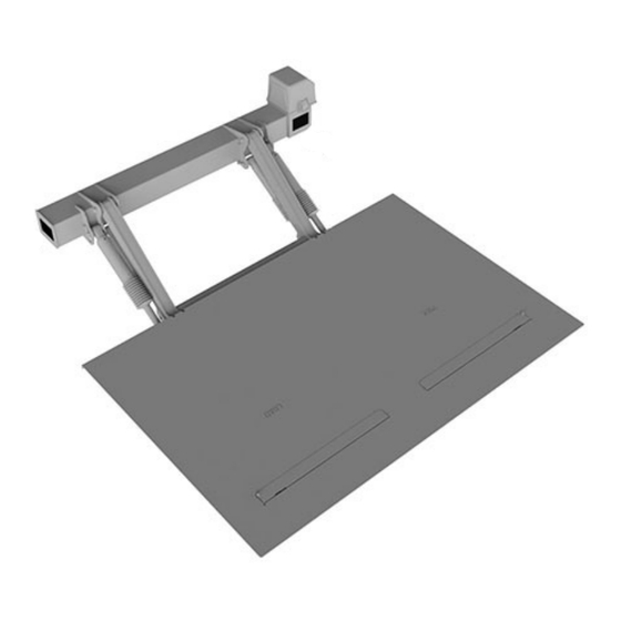
Design and Function Design and Function General The ZEPRO tail lift consists of a number of main components, namely the frame, lift arms, platform and slider profiles. The tail lift is operated electro-hydraulically. A hydraulic pump supplies hydraulic oil to the actuating hydraulic cylinders. The hydraulic system is control- led by the control system, which is operated by control devices. -
Page 22: Lift Arm
The electric lowering valve also acts as a locking device during transport. Control system ZEPRO tail lifts may be fitted with advanced types of control systems adapted to the speci- fic product. The control system controls the hydraulic system and thus the tail lift’s various functions. The system interprets the operator's pushbutton commands as well as signals from various sensors in the tail lift structure. -
Page 23: Cab And The Main Switch
Design and Function Cab and the main switch The tail lift can be fitted with a cab switch to switch control power On/Off. When the con- trol circuit is switched off, the lift is ‘locked’. The cab switch should always be in the OFF position during transport and whenever the tail lift is not in use. The tail lift can also be fitted with a main switch. It is used to switch the main power supply On/Off. When the main power supply is off, the lift is ‘locked’. If the tail lift is not fitted with a cab switch, the main switch must always be in the Off position during transport and whenever the tail lift is not in use. -
Page 24: Safety Devices
Design and Function 3.10 Safety devices 3.10.1 Two-handed operation To reduce the risk of crush injuries, the control system and its control devices require the operator to use both hands. Depending on tail lift type and configuration, this requirement may apply in all situations or where the risk of crush injuries is greatest. 3.10.2 Limiting to a single operator The tail lift may only be operated by one person at a time. -
Page 25: Controllers
Design and Function 3.11 Controllers All tail lift functions are controlled by one or more control devices. The lift can be operated by several different types of fixed, hardwired control devices and remote (radio) control devices. One of the control devices is the primary control device, which means it includes all pos- sible functions for the tail lift concerned. - Page 26 Location of fixed control device The tail lift is fitted with one or more control devices. Only control devices approved by ZEPRO may be used. Fixed control devices are installed on the vehicle superstructure or on brackets below the superstructure. The control devices must be positioned according to app- licable regulations, with a certain distance from the crush hazard area between the platform and the superstructure, but without restricting the operator’s clear view of the working area.
-
Page 27: Electric Autotilt
Design and Function 3.12 Electric autotilt The optional electric autotilt feature simplifies tail lift operation. Autotilt-down is enabled automatically when the Down function is used and when the plat- form rests on the ground, provided that the platform angle is less than 45°. This function automatically tilts the tip of the platform down towards the ground. In autotilt down, the tilt function is driven solely by gravity. -
Page 28: Overheating Protection
Design and Function 3.13 Overheating protection The hydraulic system is equipped with a thermostat which cuts control circuit power and reduces the risk of damage to the motor if it overheats, which may occur during e.g. conti- nuous, intensive use. The amount of continuous work the tail lift is able to perform is influenced by ambient temperature and the load the tail lift is exposed to. -
Page 29: Operation
ZEPRO is not liable for any injury to persons or damage to property that may result from failure of the operator or other person to comply with the recommendations, warnings and instructions set forth in this owner’s manual. -
Page 30: Max Load
750 mm from the edge of the vehicle floor. If the load’s centre of gravity is placed 1500 mm from the edge of the vehicle floor, max permissible weight decreases to 1000 kg. 4.2.1 Working in the dark CAUTION! Make sure the necessary and appropriate lighting is available when working in the dark. ZEPRO recommends fitting the tail lift with warning lights for working in poorly lit areas. Risk of injury. -
Page 31: Operator Working Position
Operation Operator working position Always position the vehicle to allow tail lift operation without danger from passing traffic. Also make sure the work area is clear. WARNING! The vehicle must be positioned to allow tail lift operation without danger from passing traffic. Risk of material damage and life-threatening injury. CAUTION! Always make sure the work area is clear during platform operation. Risk of injury. -
Page 32: Working On The Platform
To reduce the risk of foot injuries, wear safety shoes with protective steel toe-caps when wor- king on the platform. Even though the platform has a non-slip surface, take care when transfer- ring goods. ZEPRO recommends the use of anti-slip safety shoes with protective toecaps in accordance with EN ISO 20345. Risk of injury. - Page 33 Operation CAUTION! Always stand inboard of the load when rolling it onto the platform. If necessary, turn the load and hand pallet truck around on the vehicle floor before rolling them out. Standing outboard of the load when rolling it onto the platform increases the risk of tripping and falling over the edge. Risk of injury and material damage. WARNING! Make sure the load is placed securely on the platform when the tail lift is operated: When handling wheeled goods the platform must be equipped with functioning wheel stops,...
-
Page 34: Loading And Unloading From Ground Level
Operation Loading and unloading from ground level IMPORTANT It is forbidden to drive forklifts onto the platform. Risk of damage to materials. When loading and unloading with a forklift at ground level, keep the platform in its trans- port position. It is forbidden to drive forklifts onto the platform... -
Page 35: Loading And Unloading With The Platform On A Loading Dock
Operation Loading and unloading with the platform on a loading dock IMPORTANT Maximum overrunning weight = Tail lift load capacity x 0.5. Exceeding tail lift load capacity may cause material damage. It is forbidden to drive forklifts onto the platform as the load on the tail lift would be too great. Risk of material damage. - Page 36 Operation 4.6.1 Adapt the platform to the dock As the vehicle is unloaded, the platform will rise relative to the loading dock. Tilt the platform down at regular intervals. Check that the platform has sufficient overlap (min 150 mm) and that it rests safely and stably on the dock. min. 150 mm 4.6.2 Maximum tilt-down angle It is forbidden to tilt the platform down more than 10º...
-
Page 37: Moving Load From One Vehicle To Another
Operation Moving load from one vehicle to another IMPORTANT Maximum overrunning weight = Tail lift load capacity x 0.5. Exceeding tail lift load capacity may cause material damage. It is forbidden to drive forklifts onto the platform as the load on the tail lift would be too great. Risk of material damage. -
Page 38: Wheel Stop (Accessory)
Operation Wheel stop (accessory) The wheel stop is an option used to reduce the risk of wheeled loads rolling out of control when standing on the platform. WARNING! Make sure the goods are placed securely on the platform when the tail lift is operated: Goods with wheels may only be handled if the platform is equipped with working wheel stops. - Page 39 Operation 4.8.1 Sprung to open and closed position The wheel stop has a spring function that keeps in the fully open and closed position. Activation Resetting Model A Model B Model C...
- Page 40 Operation 4.8.2 Sprung to open position The wheel stop has a spring function that keeps it in the fully open position. A foot- operated latch automatically fixes the wheel stop after it has been pressed down to the closed position again. Activation Resetting Model A Model B...
- Page 41 Operation 4.8.3 Sprung to open position with dual function The wheel stop has a spring function that keeps it in the fully open position. A foot-operated latch automatically fixes the wheel stop after it has been pressed down to the closed position again. The latch can be disabled by fixing it in the narrow part of its groove. The wheel stop then always springs back to the open position after it is pressed down by a foot or wheel on goods that are rolled up on the platform when loading.
-
Page 42: Before Use
Operation Before use • On tail lifts with cab switches, switch on control power by setting the cab switch to NB! Some tail lifts may be fitted with timers that automatically switch off control power after a given time. To reset the timer and switch on control power, first set the cab switch to OFF and then back to ON. -
Page 43: Autotilt (Option)
Operation 4.11 Autotilt (Option) 4.11.1 Unloading Steps 1-7 below describe the complete unloading process from transport position to unloa- ding on the ground. Ensure that the area behind the vehicle has a level surface on which the platform can rest. Move the platform to a horizontal position level with the floor of the vehicle. - Page 44 Operation 4.11.2 Loading Steps 1-7 below describe a complete loading process from transport position to loading onto the vehicle. Ensure that the area behind the vehicle has a level surface on which the platform can rest. Move the platform to its horizontal position. Use the Down function to lower the platform until the castors touch the ground and continue holding the control button until the top of the platform reaches the ground (autotilt down).
-
Page 45: Fixed Controller (Cd20)
Operation 4.12 Fixed controller (CD20) The controller controls all tail lift functions. The control device is fitted with dead-man’s buttons; when a button is released, tail lift movement stops immediately. The controller has a customised layout for mounting on the left and right sides of the vehicle. Control device installed on the right side of the vehicle Control device installed on the left side of the vehicle FUNCTIONS 1. - Page 46 Operation 4.12.1 Switching from transport position to working position This procedure describes how to prepare the tail lift for use following transport. The illus- trations show a control device installed on the right side of the vehicle. Down Depress and hold down the ‘Down’ button (3). The platform is lowered at an even pace. Lower the platform 5-10 cm to release it from the transport locks.
- Page 47 Operation 4.12.2 Operation in the working position This procedure describes how to operate the tail lift in the working position. The illustra- tions show a control device installed on the right side of the vehicle. Depress and hold down the ‘Up’ button (1). The platform is then raised at an even pace. Down Depress and hold down the ‘Down’...
- Page 48 Operation 4.12.3 Moving from the working position to the transport position This procedure describes how to prepare the tail lift for transport after loading or unlo- ading. The illustrations show a control device installed on the right side of the vehicle. First operate the tail lift up or down until the platform is 5-10 cm above the ground.
-
Page 49: Operating With The Fixed Control Device (Cd3)
Operation 4.13 Operating with the fixed control device (CD3) The control device governs all tail lift functions. The control device is fitted with dead-man's buttons; when a button is released, tail lift movement stops immediately. Control device with main switch (optional). Used for switching off the main power supply to the tail lift. FUNCTIONS 1. - Page 50 Operation 4.13.1 Switching from transport position to working position This procedure describes how to prepare the tail lift for use following transport. Down Depress and hold down the ‘Down’ button (3). The platform is lowered at an even pace. Lower the platform 5-10 cm to release it from the transport locks. IMPORTANT It is important to lower the platform to clear the transport stops before moving it outwards.
- Page 51 Operation 4.13.2 Operation in the working position This procedure describes how to operate the tail lift in the working position. Depress and hold down the ‘Up’ button (1). The platform is then raised at an even pace. Down Depress and hold down the ‘Down’ button (3). The platform is lowered at an even pace. Down Tilt down Depress and hold down the ‘Tilt’...
- Page 52 Operation 4.13.3 Moving from the working position to the transport position This procedure describes how to prepare the tail lift for transport after loading or unloading. First operate the tail lift up or down until the platform is 5-10 cm above the ground. Fold the platform together and then operate the tail lift as described below.
-
Page 53: Operating With The Coiled Cable Control Device (Cd9)
Operation 4.14 Operating with the coiled cable control device (CD9) The control device is used when the tail lift is in the working position and to control the Up, Down and Tilt functions. The control device is fitted with dead-man's buttons; when a but- ton is released, tail lift movement stops immediately. FUNCTIONS Tilt Down... - Page 54 Operation 4.14.1 Operation in the working position This procedure describes how to operate the tail lift with the coiled cable control device (CD 10). Depress and hold down the ‘Up’ button (1). The platform is then raised at an even pace. Down Depress and hold down the ‘Down’...
- Page 55 Operation Tilting down Depress and hold down the ‘Tilt’ (2) and ‘Down’ (3) buttons in that order. The platform is then tilted down at an even pace. Tilt down Tilting up Depress and hold down the ‘Tilt’ (2) and ‘Up’ (1) buttons in that order. The platform is then tilted up at an even pace.
-
Page 56: Operating With The Coiled Cable Control Device (Cd10)
Operation 4.15 Operating with the coiled cable control device (CD10) The control device is used when the tail lift is in the working position and to control the Up and Down functions. The control device is fitted with dead-man's buttons; when a button is released, tail lift movement stops immediately. FUNCTIONS Down... - Page 57 Operation 4.15.1 Operation in the working position This procedure describes how to operate the tail lift with the coiled cable control device (CD 10). Depress and hold down the ‘Up’ button (1). The platform is raised at an even pace. Down Depress and hold down the ‘Down’...
-
Page 58: Operating With The Foot Operated Control Device (Cd14)
Operation 4.16 Operating with the foot operated control device (CD14) The control device is used when the tail lift is in the working position and to control the Up and Down functions. The control device is fitted with dead-man's buttons; when a button is released, tail lift movement stops immediately. FUNCTIONS Down Activation... - Page 59 Operation 4.16.1 Operation in the working position This procedure describes how to operate the tail lift with the foot operated control device (CD 14). Depress and hold down the ‘Activation’ (3) and ‘Up’ (1) buttons in that order. The platform is raised at an even pace.
-
Page 60: Operating With The Radio Control Device (Cd11)
Operation 4.17 Operating with the radio control device (CD11) The control device is used when the tail lift is in the working position and to control the Up, Down, Tilt and Lock/Unlock functions. Buttons 1-3 are dead-man's buttons; when a button is released, tail lift movement stops immediately. - Page 61 Operation 4.17.2 Operation in the working position This procedure describes how to operate the tail lift with the radio control device (CD 11). Press the ‘Up’ button (1). The platform is raised at an even pace. Down Press the ‘Down’ button (3). The platform is lowered at an even pace. Down...
- Page 62 Operation Tilting up Depress and hold down the ‘Tilt’ (2) and ‘Up’ (1) buttons in that order. The platform is then tilted up at an even pace. Tilt up Tilting down Depress and hold down the ‘Tilt’ (2) and ‘Down’ (3) buttons in that order. The platform is then tilted down at an even pace.
-
Page 63: Service And Maintenance
This manual includes ZEPRO’s recommendations for checks, lubrication and service. 5.3 Daily checks 5.4 Weekly checks 5.5 Lubrication 5.6 Service Hydraulic oil If the hydraulic oil needs to be replenished, only the oil recommended by ZEPRO is permit- ted to be used. Hydraulic systems with hydraulic oil tanks without labelling are only permitted to be filled with highly refined mineral oil (art. no. 21963, 1 litre). Hydraulic systems with hydraulic oil tanks marked with a specification for the hydraulic oil are only permitted to be filled with the oil specified on the label. -
Page 64: Before Starting Work
Service and maintenance Before starting work IMPORTANT Carry out the following before starting any service or maintenance: • Lower and tilt the platform down so that it rests on the ground to reduce pressure in the hydraulic system to a minimum. •... -
Page 65: Daily Check
24 Check that the platform is clean and safe to access. Remove any snow, mud, dirt, rubbish or slippery fluids. ZEPRO recommends the use of anti-slip safety shoes with protective toecaps in accordance with EN ISO 20345. Risk of personal injury. Check the wheel stops (accessory) for function and damage. Make sure that the wheel stops do not jam, lubricate if necessary with thin penetrating oil. -
Page 66: Weekly Check
Service and maintenance Weekly check Carry out the following checks: Test all tail lift functions using all control devices. Contact a qualified service engineer for troubleshooting or repair. Check hoses, connections and cylinders for cracks and leaks. Contact a qualified service engineer for troubleshooting or repair. Check the hydraulic cylinder boots for damage and secure fit. Contact a qualified ser- vice engineer for troubleshooting or repair. Check operation of the cab switch and main switch. Their function is described in sec- tion ”3.8 Cab and the main switch” on page 23. Contact a qualified service engineer for troubleshooting or repair. -
Page 67: Lubrication
Interval At a minimum, lubrication must be done every 3 months. More frequent intervals may be necessary when driving in aggressive surroundings or the lift is washed often. Contact ZEPRO for advice. 5.5.3 Before lubrication Before lubricating, clean the lift, especially the lubrication points and grease nipples. -
Page 68: Service
Service the lift regularly to keep maintenance costs low, safety high and product life long. An annual service must be carried out by a ZEPRO approved workshop for the warranty to remain valid. For information about the nearest workshop, visit the ZEPRO website or contact your distributor. -
Page 69: Marking
Marking Marking Below is an overview showing the location of the different markings. Marking illustrations can be found under the relevant subheadings in the following pages. www.hiab.co 2020-03-04 55057TL... -
Page 70: Maximum Load Rating
Marking Maximum load rating The marking shows the max permissible load on the platform. The tail lift must never be laden with weights higher than permitted by the marking. Max permissible load only applies at a specific distance from the vehicle body (load centre distance). Behind this point, max permissible load is reduced. Refer to the marking on the platform or vehicle. -
Page 71: Identification Plate
Marking Identification plate Type plates are mounted on the tail lift frame and on the cab door pillar. The identification plate contains the follo- wing information: • Type of lift • Max. permitted load in kg • Serial number • Year of manufacture • Address and tel. no. of manufacturer •... -
Page 72: Control Device Sticker
Marking Control device sticker The control device sticker is affixed next to or on the relevant control device depending on its type. The stickers are available in standard versions and in reversed version (Option) for affixing on the opposite side of the vehicle. Control device sticker for CD 3 Control device sticker for CD 9 Control device sticker for CD 19 Control device sticker for CD 10... - Page 73 Marking 6.5.1 Autotilt additional sticker There is an additional sticker affixed next to the control device sticker on tail lifts fitted with autotilt. The stickers are available in standard versions and in reversed version (Option) for affixing on the opposite side of the vehicle. Additional Auto-tilt sticker for CD 3 Additional Auto-tilt sticker for CD 9 Additional Auto-tilt sticker for CD 19...
-
Page 74: Danger Area
Marking Danger area The sticker is affixed on the inside of the superstructure next to the manual control device where fitted. The sticker informs about the hazards area between the vehicle floor and platform where the risk of crush injuries is especially great when operating the tail lift. www.hiab.com 55061TL 2020-05-14 Danger area Warning flags Warning flags are mounted near the tip of the platform and the left and right edges to improve conspicuity when the platform is in the horizontal position. -
Page 75: Troubleshooting
Troubleshooting Troubleshooting The table below provides information about the most common problems and suggests steps to resolve them. If this simple guide does not help or in case of doubt, contact a qualified service engineer. Problem Probable cause Action Set the cab switch and/or main switch Cab switch and/or in the On position. -
Page 76: Technical Specifications
Technical specifications Technical specifications Noise declaration Average emission sound pressure level does not exceed 70 dB Noise Directive 2000/14/EC Noise measurement according to EN ISO 11200-11204 Measurement was carried out in accordance with EN ISO 3741-3746 Class II... -
Page 77: Product Discontinuation
Product discontinuation Product discontinuation General Tail lift disassembly must be carried out by personnel with the necessary knowledge and expe- rience to ensure no dangerous incidents or environmental impact can occur due to ignorance. Applicable regulations and legislation When disassembling and/or recycling, comply with local and national regulations and guidelines. - Page 78 Product discontinuation 9.2.2 Disassembly Disassembly is best carried out in the following order: Platform Hydraulic cylinders and hoses Hydraulic unit Lift arms Frame including brackets CAUTION! Always use lifting aids and exercise great caution when lifting heavy loads. Make sure that heavy parts are completely resting on the ground or secured by a lifting device before removing shafts, bolts or other fasteners.
-
Page 79: Service Record
Year 1 Service record Service Protocol L-Service (annual) Customer: Vehicle: Reg.No: Lift model: Prod.No: C=Check R=Replace L=Lubrication * If the lift has the equipment See instructions for Service points Information Comments resp. lift models Mecanics (Visual inspection of any cracks and / or damage) IE-0110 IE-0105 / IE-0104 1.1 Mounting bracket... - Page 80 If there are remarks concerning any of the service items, indicate any action below: Service check (in the table below, confirm actions have been carried out for each service item. Service Remark/Action item Checks and actions have been carried out: ........................... Date Signature Company stamp...
- Page 81 Year 2 Service Protocol L-Service (annual) Customer: Vehicle: Reg.No: Lift model: Prod.No: C=Check R=Replace L=Lubrication * If the lift has the equipment See instructions for Service points Information Comments resp. lift models Mecanics (Visual inspection of any cracks and / or damage) IE-0110 IE-0105 / IE-0104 1.1 Mounting bracket...
- Page 82 If there are remarks concerning any of the service items, indicate any action below: Service check (in the table below, confirm actions have been carried out for each service item. Service Remark/Action item Checks and actions have been carried out: ........................... Date Signature Company stamp...
- Page 83 Year 3 Service Protocol XL-Service Incl. replacement of parts in Service Kit Customer: Vehicle: Reg.No: Lift model: Prod.No: C=Check R=Replace L=Lubrication * If the lift has the equipment **If the service kit contains the detail See instructions for Service points Information Comments resp.
- Page 84 If there are remarks concerning any of the service items, indicate any action below: Service check (in the table below, confirm actions have been carried out for each service item. Service Remark/Action item Checks and actions have been carried out: ........................... Date Signature Company stamp...
- Page 85 Year 4 Service Protocol L-Service (annual) Customer: Vehicle: Reg.No: Lift model: Prod.No: C=Check R=Replace L=Lubrication * If the lift has the equipment See instructions for Service points Information Comments resp. lift models Mecanics (Visual inspection of any cracks and / or damage) IE-0110 IE-0105 / IE-0104 1.1 Mounting bracket...
- Page 86 If there are remarks concerning any of the service items, indicate any action below: Service check (in the table below, confirm actions have been carried out for each service item. Service Remark/Action item Checks and actions have been carried out: ........................... Date Signature Company stamp...
- Page 87 Year 5 Service Protocol L-Service (annual) Customer: Vehicle: Reg.No: Lift model: Prod.No: C=Check R=Replace L=Lubrication * If the lift has the equipment See instructions for Service points Information Comments resp. lift models Mecanics (Visual inspection of any cracks and / or damage) IE-0110 IE-0105 / IE-0104 1.1 Mounting bracket...
- Page 88 If there are remarks concerning any of the service items, indicate any action below: Service check (in the table below, confirm actions have been carried out for each service item. Service Remark/Action item Checks and actions have been carried out: ........................... Date Signature Company stamp...
- Page 89 Year 6 Service Protocol XL-Service Incl. replacement of parts in Service Kit Customer: Vehicle: Reg.No: Lift model: Prod.No: C=Check R=Replace L=Lubrication * If the lift has the equipment **If the service kit contains the detail See instructions for Service points Information Comments resp.
- Page 90 If there are remarks concerning any of the service items, indicate any action below: Service check (in the table below, confirm actions have been carried out for each service item. Service Remark/Action item Checks and actions have been carried out: ........................... Date Signature Company stamp...
-
Page 91: Own Remarks
Own remarks .............................................................................................................................................................................................................................................................................................................................................................................................................................................................................................................................................................................................................................................................................................................................................................................. -
Page 92: Product Approval
Product approval Product approval EC Declaration of Conformity. ZEPRO, Z-Lyften Produktion AB Allévägen 4, SE 844 41 Bispgården SWEDEN hereby declares that tail lift ZS MK2, ZT MK2, ZD 15/20, ZD 150/200, SZFT/SZFTS 200 with serial numbers from 380000 onwards, are manufactured in compliance with the following EC directives: •... -
Page 93: Declaration Of Conformity
Declaration of conformity Declaration of conformity In accordance with UK Government Guidance. Product Model / Type: Product: ZEPRO Tail lift Model: ZS MK2 ZT MK2 ZD 15/20 ZD 150/200 SZFT/SZFTS 200 Serial: 380000 onwards Manufacturer: Name: Z-Lyften Produktion AB Address: Allévägen 4, SE844 41... -
Page 94: Declaration Of Conformity During Assembly
Because ZEPRO’s installation instructions have been followed and any modifications are approved by ZEPRO, this document constitutes confirmation that the tail lift and its installa- tion are in compliance with the following directives. Machinery Directive 2006/42/EG The installer hereby certifies that: - installation was carried out according to ZEPRO’s instructions - installation/delivery inspections have been performed ..........................Installer's signature Date .............. - Page 96 BUILT TO PERFORM ZEPRO, Del and Waltco are Hiab tail lift brands. Hiab is a world-leading supplier of equipment, intelligent services and digital solutions for on-road load handling. As an industry pioneer, our company commitment is to increase the efficiency of...
Need help?
Do you have a question about the 78826TL and is the answer not in the manual?
Questions and answers