Table of Contents
Advertisement
Quick Links
Advertisement
Table of Contents

Related Manuals for Elsner Cala KNX M-T CH Series


Summary of Contents for Elsner Cala KNX M-T CH Series
- Page 1 Cala KNX M-T CH Push Button with Temperature Sensor Cala KNX M1-T CH Cala KNX M2-T CH Item numbers 70861 (white), 70863 (black) Item numbers 70871 (white), 70873 (black) Cala KNX M4-T CH Item numbers 70881 (white), 70883 (black) Installation and Adjustment...
-
Page 3: Table Of Contents
7.6.1. AND logic 1+2 and OR logic outputs 1+2 ..........21 7.6.2. OR LOGIC connection inputs ..............23 Elsner Elektronik GmbH • Sohlengrund 16 • 75395 Ostelsheim • Germany Cala KNX M-T CH push button • from version 0.1.4, from application 1.0... - Page 4 The change status (software version and date) can be found in the contents footer. If you have a device with a later software version, please check www.elsner-elektronik.de in the menu area "Service" to find out whether a more up-to- date version of the manual is available.
-
Page 5: Description
Configuration is made using the KNX software as of ETS 5. The product file can be downloaded from the ETS online catalogue and the Elsner Elektronik website on www.elsner-elektronik.de in the “Service” menu. There you will also find the pro- duct manual. -
Page 6: Area Function
Description 1.0.1. Area function If the area function in ETS has been activated, another function is available alongside the regular key functions. This is triggered by touching multiple keys, e.g. if you touch the sensor with the palm of your hand. Using the area function If a key is pressed and another (different) key is touched within 0.2 seconds, the action set in the ETS is performed for the area operation (See Fig. -
Page 7: Technical Data
Installation and commissioning • Mounting adapter with screws Additionally required (not included in the deliverables): • Cover frame (for insert 60 x 60 mm) and mounting plate (77 mm) for swiss installation standard • Inlet box 1.2. Technical data Casing Genuine glass, plastic Colours •... -
Page 8: Installation Location
Elsner Elektronik is not liable for any changes in norms and standards which may occur after publication of these operating instructions. 2.1. Installation location The Cala KNX M-T CH push button is made for wall mounting in an inlet box. -
Page 9: Device Structure
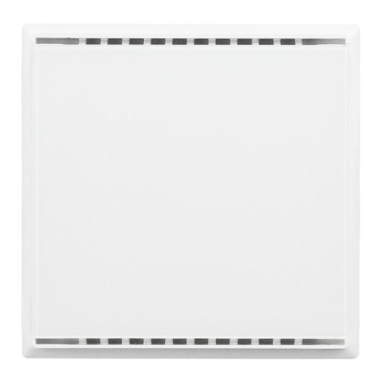
Installation and commissioning 2.2. Device structure 2.2.1. Casing Fig. 2: Front Ventilation slit (top and bottom) Touch areas with LEDs Fig. 3: Rear Mounting adapter KNX terminal BUS +/- Catches Programming LED (recessed) Programming LED (recessed) for teaching the device 2.3. -
Page 10: Commissioning
Commissioning Turn the screws little way into the mounting adapter. Fig. 4 Hook the mounting adapter into the mounting plate of the switch system and tighten the screws. Fig. 5 Screw the mounting plate onto the in- let box Position the frame of the switching programme. Connect the bus line +/- to the black- red plug. -
Page 11: Disposal
Disposal Disposal After use, the device must be disposed of in accordance with the legal regulations. Do not dispose of it with the household waste! Cala KNX M-T CH push button • Version: 25.04.2022 • Technical changes and errors excepted. -
Page 12: Transfer Protocol
Transfer protocol Transfer protocol Units: Temperatures in degrees Celsius 6.1. List of all communications objects Abbreviation flags: Communication Read W Write Transmit U Update Text Function Flags DPT type Size Software version Output R-CT [217.1] DPT_Version 2 Bytes Only with Cala KNX M2-T CH and Cala KNX M4-T CH Area operation on/off Input -WC-... - Page 13 Transfer protocol Text Function Flags DPT type Size Temperature sensor: meas- Output R-CT [9.1] DPT_Value_Temp 2 Bytes ured value minimum Temperature sensor: meas- Output R-CT [9.1] DPT_Value_Temp 2 Bytes ured value maximum Temperature sensor: meas- Input -WC- [1.17] DPT_Trigger 1 Bit ured value min./max.
- Page 14 Transfer protocol Text Function Flags DPT type Size Push-button 4 encoder 8 bit Output R-CT [5.10] DPT_Value_1_U- 1 Byte count Push-button 4 encoder 16 bit Output R-CT [9] 9.xxx 2 Bytes Push button 4 Scene Output R-CT [18.1] DPT_SceneCon- 1 Byte trol For all models Logic input 1...
-
Page 15: Setting The Parameters
Setting the parameters Setting the parameters 7.1. Behaviour on power failure/ restoration of power Behaviour following a failure of the bus power supply: The device sends nothing. Behaviour on bus restoration of power and following programming or reset: The device sends all outputs according to their send behaviour set in the parameters with the delays established in the "General settings"... -
Page 16: Push Button
Setting the parameters At and above change of 0.1°C • 0.2°C • 0.5°C • ... • 5.0°C (if sent on change) Send cycle 5 s • 10 s • ... • 2 h (if sent periodically) The minimum and maximum readings can be saved and sent to the bus. Use the "Reset temperature min/max. -
Page 17: Push Button 1 / 2 / 3 / 4
Setting the parameters 7.4.1. Push button 1 / 2 / 3 / 4 Set the function of the push button. Function • Switch • Selector switch • Blind • Shutters • Awning • Windows • Dimmer • 8-bit encoder • 16-bit encoder •... - Page 18 Setting the parameters Use additional function for button held down Time between tap and hold (0.1 sec) 0 ... 50; 10 Command when pressing the button Do not send message Command when releasing before time • Switch expires • Do not send message Command when pressing the button •...
- Page 19 Setting the parameters Command • Brighter • Darker • Lighter/Darker Time between switching and dimming 0 ... 50; 5 (in 0.1 s) Repeat the dim command No • Yes Repeat the dim command with a long hold every 0.1 s • ... • every 0.5 s • ... • every 2 s of the button Dim by 100% •...
-
Page 20: Control Modes For Drive Control
Setting the parameters 7.4.2. Control modes for drive control Behaviour on button actuation in standard control mode: short: hold Blind Stop/Step Up or down Shutters Stop Up or down Awning Stop In or out Windows Stop Closed or open Standard: If briefly operated, the drive will move incrementally or stops. -
Page 21: Leds
Setting the parameters Fig. 6 Time interval comfort mode diagram Time 1 Time 2 1 + 2 Point in time 0: Actuate of button, start of time 1 Release before time 1 expired: step (or stop if drive is moving) Point in time 1: End of time 1, start of time 2 Moving command... -
Page 22: Logic
Setting the parameters Use objects No • Yes Object value on/off after reset 0 • 1 (if objects are used) Use automatic switch-off after pressing a No • Yes button Switch off after (is automatic switch off is 1 ... 255; 30 secs. after pressing used) All LEDs individually controllable This is where you set the brightness of the LEDs, whether objects are used and whether... -
Page 23: And Logic 1+2 And Or Logic Outputs 1+2
Setting the parameters 7.6.1. AND logic 1+2 and OR logic outputs 1+2 The same setting options are available for AND and OR logic. Each logic output may transmit one 1-bit or two 8-bit objects. Determine what the out put should send if logic = 1 and = 0. 1. - Page 24 Setting the parameters Set the output send pattern. Transmission behaviour • on change of logic • on change of logic to 1 • on change of logic to 0 • on change of logic and periodically • on change of logic to 1 and periodically •...
-
Page 25: Or Logic Connection Inputs
Setting the parameters 7.6.2. OR LOGIC connection inputs The OR logic connection inputs are the same as those for the AND logic. Additionally, the following inputs are available for the OR logic: Switching output AND logic 1 Switching output AND logic 1 inverted Switching output AND logic 2 Switching output AND logic 2 inverted Cala KNX M-T CH push button •... - Page 26 Questions about the product? You can reach the technical service of Elsner Elektronik under Tel. +49 (0) 70 33 / 30 945-250 or service@elsner-elektronik.de We need the following information to process your service request: • Type of appliance (model name or item number) •...
Need help?
Do you have a question about the Cala KNX M-T CH Series and is the answer not in the manual?
Questions and answers