
Related Manuals for Elsner Solexa 230V


Summary of Contents for Elsner Solexa 230V
- Page 1 Solexa 230V Shading Control Item numbers 10110, 10130, 10131 Installation and Adjustment...
-
Page 2: Table Of Contents
Description ..................... 3 Scope of supply ........................... 3 Commissioning procedure ......................... 3 Options for connection and control ....................3 Overview of available automatic functions ..................4 Operation ....................5 Key functions and display symbols of the meteorological data display ........5 Display of lightness and wind speed .................... - Page 3 Attaching the mount .......................... 31 Preparation of the weather station ....................32 Connection of voltage supply and drive mechanism ..............33 Mounting of the weather station ...................... 34 Details for the installation of the weather station ................35 Installation of operating unit ..................35 Notes on radio installations ..................
-
Page 4: Description
Description The Solexa shading control system has been developed for the automatic control of awnings or blinds and for comfortable manual operation. The control system offers a highest degree of flexibility for installation and setting and may therefore be adjusted individually to different conditions. Please anxiously use this instruction manual in order to adjust the automatic function to your require- ments. -
Page 5: Overview Of Available Automatic Functions
The following environmental parameters are measured and displayed: • Outdoor and indoor temperature • Lightness • Wind speed • Precipitation Solexa may be deployed in the control system XS as control centre and as transducer. In this case, the control is upgraded with motor control units and operating units of system XS. -
Page 6: Operation
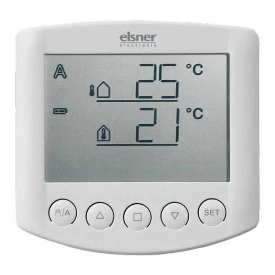
Operation Key functions and display symbols of the meteorological data display Outdoor Temperature Automatic Manual Indoor Temperature Battery Rain alarm Wind alarm Manual/ Stop Down Setting Automatic The basic position of the operating unit of the control system displays the current outdoor temperature (upper line) and the indoor temperature (lower line) as well as the function mode (automatic or manual), the battery load and the current alarm messages for rain or wind. -
Page 7: Display Of Lightness And Wind Speed
Manual mode activated. The connected drive mechanism was operated manually (with arrow keys) or key was pressed. Thus, the automatic functions are deactivated, there is no control in terms of lightness or temperature. The safety functions rain alarm and wind alarm are still activated. -
Page 8: Manual Operation
Manual operation Manual control as well as the presetting of the automatic functions and the basic setting of the connected shading is accomplished with the keys of the operating unit. Move shading manually Stop Down The connected awning or blind may be manually operated with the keys . -
Page 9: Settings (Default Setting, Automatic)
In order to get to the display, press key twice shortly in automatic mode ( and once shortly in manual mode ( As long as the display shows , manual operating commands of this operating unit are submitted to all drive mechanisms in system XS. During this display, use the keys in order to centrally operate all drive mechanisms. -
Page 10: Setting Of Automatic
Setting of automatic For the awning or blind to shade optimally, the values for automatic operation must be adjusted to the local conditions. The following settings are queried one after the other: A. Lightness for the shading B. Extension delay C. - Page 11 You are in the automatic settings Leave Confirm/ next You may leave the automatic settings at any time by pressing the key . The accomplished changes of the values are not saved in this case. If you do not press any key in the automatic settings for 5 minutes, the display automatically changes to temperature display.
-
Page 12: Lightness For The Shading
A. Lightness for the shading In the automatic settings, you must indicate at first the lightness from which shading shall start. Sun intensity is displayed in kilolux (kLux). The value of 1 kLux is already reached in case of a cloudy sky, 20 kLux indicates that the sun has just come out and 100 kLux are achieved with blue sky at noon. -
Page 13: Extension Delay
B. Extension delay After the setting of the lightness, now enter the delay time for the extension of the shading. The purpose of the delay is that the shading does not permanently extend and retract in case of fast changing lightness conditions. The presetting for the extension is 1 minute. -
Page 14: Indoor Temperature Block
automatic settings) for the extended shading to retract. Thus, clouds passing by are „ignored”. Adjust the value with (higher) and (lower). Then press in order to access the setting of the next parameter. D. Indoor temperature block After the setting of the retraction delay, now select the indoor temperature below which shading shall be prevented. -
Page 15: Outdoor Temperature Block
E. Outdoor temperature block After the setting of the indoor temperature block, now select the outdoor temperature below which shading shall be prevented. The outdoor temperature block is important for exterior sun protection systems. In case of frost, the awning or blind may freeze in the slide rails. If the shading is then moved, it may be damaged. -
Page 16: Wind Alarm
F. Wind alarm After the setting of the outdoor temperature, now provide the value for the wind protection function. The wind alarm protects the exterior shadings from damage. If the indicated wind value is exceeded, the awning or blind is retracted and manual operation is blocked. -
Page 17: Rain Alarm
Table for wind speeds Description m/sec km/h Beaufort knots Calm < 0,3 < 1,1 < 1 Almost calm 0,3-1,5 1,1-5,4 Very weak wind 1,6-3,3 5,5-11,9 Weak wind 3,4-5,4 12,0-19,4 7-10 Moderate wind 5,5-7,9 19,5-28,4 11-16 Fresh wind 8,0-10,7 28,5-38,5 17-21 Very fresh wind 10,8-13,8 38,6-49,7... -
Page 18: Storage Of Automatic Settings
H. Storage of automatic settings At the end of the entry of automatic settings, the symbol (save) asks whether the accomplished setting shall be saved. Press the key in order to save your entered data and to access the meteorological data display. With , you quit the automatic settings without saving. -
Page 19: Basic Settings
Basic settings These are the basic settings of the device for the commissioning of the control system. The following settings are queried one after the other: 1. Radio connection to the weather station 2. Rotational direction of the motor 3. Operating direction 4. - Page 20 You are in the basic settings Change Leave Confirm/ next You may leave the basic settings at any time by pressing the key . The accomplished changes are not saved in this case. If you do not press any key in the basic settings for 5 minutes, the display automatically changes to temperature display.
-
Page 21: Radio Connection To The Weather Station
1. Radio connection to the weather station The first step is the teaching in (or later the deletion) of the radio connection. Select the desired step with the key: (continue) in order to skip this step, (learn) in order to teach in a radio connection to the weather station, (clear) in order to delete an existing radio connection. -
Page 22: Delete All Radio Connections Of The Weather Station
As soon as you have confirmed (clear) with the key, the radio connection is deleted. The display automatically skips to (learn) in order to enable the teaching in of a new connection. Delete all radio connections of the weather station You can delete all radio connections of the weather station with operating units and hand-held transmitters at once by pressing the programming key for longer than 5 seconds. -
Page 23: Operating Direction
3. Operating direction After the setting of the rotational direction of the motor, now select whether the shading extends from top to bottom or from bottom to top. Depending on the model, shadings may extend from top to bottom or from bottom to top. -
Page 24: Operating Command In Case Of Wind Or Rain Alarm
4. Operating command in case of wind or rain alarm After the setting of the operating direction, you may now select whether the operating command in case of wind or rain alarm is temporary or permanent. After the wind or rain alarm has been activated, the shading is retracted. The operating command for the connected drive mechanism either ends after 4 minutes or is permanently maintained as long as the alarm message exists. -
Page 25: Sending Of Meteorological And Automatic Data
5. Sending of meteorological and automatic data After the setting of the operating command in case of wind or rain alarm, you may now select, whether the meteorological data and the automatic commands of Solexa shall be submitted by radio to the motor control units of system XS. Leave this display at if Solexa is used as conventional single-channel control system. -
Page 26: Shading Position
6. Shading position After the setting of the sending of meteorological and automatic data, you may now teach in a shading position. You may determine an individual position for awnings or blinds up to which the shading is extended in automatic mode. In case of blinds with slats, an additional aperture angle of the slats may be determined (reversing). -
Page 27: Retracted Position
6.1. Retracted position After having confirmed (learn), the command (open) appears. At first, completely retract the awning or blind so that there is no shading. Press key in order to access the next setting step. 6.2. Setting of the desired position The command (close) appears. -
Page 28: Slat Angle
6.3. Slat angle Command (reversing) appears. In case of blinds with slats, now open the slats in the desired angle. In case of awnings or if slats shall not be opened, do not move the shading. Then press the key in order to complete the setting of the shading position. 7. -
Page 29: Safety Instructions For Automatic And Alarm Functions
Safety instructions for automatic and alarm functions In case of power fail at the weather station, the control system cannot actuate the connected drive mechanisms anymore! If the complete scope of functions must be guaranteed in case of power fail, an emergency power generator with an according switch-over from mains operation to emergency operation must be installed. -
Page 30: Installation And Commissioning
The control must only be operated as stationary system, i.e. only in a fitted state and after completion of all installation and start-up works, and only in the environment intended for this purpose. Elsner Elektronik does not assume any liability for changes in standards after publication of this instruction manual. -
Page 31: Installation Of Weather Station And Connection Of The Drive Mechanism
Installation of weather station and connection of the drive mechanism Position Select an assembly site at the building where wind, rain and sun may be collected by the sensors unobstructedly. Do not assemble any construction components above the weather station from where water may drop on to the rain sensor after it has stopped raining or snowing. -
Page 32: Attaching The Mount
When pole mounting: curved side on pole, collar downward. An additional, optional accessory available from Elsner Elektronik is an articulated arm for flexible wall, pole or beam mounting of the weather station. Example of the use of a mounting arm: Due to flexible ball joints, the sensor can be brought into ideal position. -
Page 33: Preparation Of The Weather Station
Example for the application of the hinge arm mounting: With the hinge arm mounting, the weather station projects from beneath the roof. Sun, wind and precipitation can be measured unhindered by the sensors. Example for the application of the hinge arm mounting: Pole-mounting with... -
Page 34: Connection Of Voltage Supply And Drive Mechanism
Several drive mechanisms may be connected in parallel. In case of the parallel connection of motors, please observe whether a group control relay is specified by the motor manufacturer. Group control relays may be provided by Elsner Elektronik or the motor manufacturer. -
Page 35: Mounting Of The Weather Station
Motors with a rated input of more than 1000 Watt must be operated with a relay or contactor with own feeder. We offer appropriate power supply units for DC drive mechanisms. In case of need, please indicate the type of motor, manufacturer and – if available – technical data. -
Page 36: Details For The Installation Of The Weather Station
Details for the installation of the weather station Do not open the weather station if water (rain) might ingress: Even some drops might damage the electronic system. Observe the correct installation. Wrong installation might destroy the weather station and the control electronics. Please take care not to damage the temperature sensor (small circuit board at the bottom part of the housing.) when mounting the weather station. -
Page 37: Commissioning
Commissioning If a device is brought from a cold to a warm area, condensation can form. Before starting the device up, please ensure there is no moisture inside it (if necessary leave to dry). After the system has been wired and the connections have been checked, please proceed as follows: •... -
Page 38: Sensor Testing
Now you are in basic settings. Proceed as described in the basic settings chapter „1. Radio connection to weather station“ (p. 20). • Then check the function of the sensors (see next chapter). Sensor testing In case of malfunctions of the sensors, the display shows error messages instead of values. -
Page 39: Rain Sensor Testing
Rain sensor testing Humidify one or several of the golden sensor areas in the cover of the weather station. The symbol (rain alarm) appears in the display. For this purpose, the rain alarm in the automatic settings must be activated (this is the presetting as delivered, also see chapter "G. -
Page 40: Service
Service Service and maintenance Weather station The weather station must regularly be checked for dirt twice a year and cleaned if necessary. In case of severe dirt, the wind sensor may not work properly anymore, there might be a permanent rain message or the station may not identify the sun anymore. -
Page 41: Error Messages
Observe the correct polarity of the batteries. You need two standard batteries (1.5 V) or accumulators (1.2 V) of type AA (Mignon/ LR6). Close the housing by fitting the front panel with circuit board from above into the rear panel. The locking must engage with a clearly noticeable “click”. Error messages Despite the values for temperature, lightness or wind speed, the display may indicate error messages in the meteorological data display. - Page 42 Cause: No radio connection between operating unit and weather station. The weather station is out of order (e.g. has no voltage) or the radio connection is interrupted or has not yet been taught in. Action: The error may only be corrected by a qualified person for electronics.
-
Page 43: Query Service Data
Query service data The software version of the operating unit and the weather station may be indicated in the display. From the basic settings you may get to the service menu by a long pressing of (3 seconds). At first, the software version of the operating unit ( , panel) is indicated, after the short pressing of , the... -
Page 44: Weather Station
Ambient air humidity: max. 80% RH, avoid bedewing Operating voltage: 2 x 1.5 V (2 batteries, AA/Mignon/LR6) or 2 x 1.2 V (2 rechargeable batteries, AA/Mignon/LR6) Radio frequency: 868.2 MHz Weather station Housing: Plastic material Colour: White / translucent Mounting: On-wall Protection category: IP 44... -
Page 45: Connection Diagram For Weather Station
Connection diagram for weather station The operating unit is battery-powered. The communication between operating unit and weather station is accomplished by radio. -
Page 46: View Of Rear Side And Drill Hole Plan For The Weather Station
View of rear side and drill hole plan for the weather station All values are in mm, deviations due to technical reasons are possible. -
Page 47: View Of Rear Side And Drill Hole Plan For The Operating Unit
View of rear side and drill hole plan for the operating unit All values are in mm, deviations due to technical reasons are possible. -
Page 48: Connection Samples For Several Drive Mechanisms As Group
Connection samples for several drive mechanisms as group... -
Page 49: Connection Samples For Centralised Control With Imsg 230
Connection samples for centralised control with IMSG 230 Simple central control with motor control units at the drive output of Solexa weather station:... - Page 50 Central control with group formation with motor control units at the drive output of Solexa weather station: Single Control Units Group Control Units Central Control Unit Control System...
-
Page 51: Personal Setting Data Of The Automatic
Personal setting data of the automatic Shading if lightness exceeds kLux Delay time of extension Delay time of retraction Shading if indoor temperature exceeds °C Outdoor temperature block below °C Wind alarm from m/sec Rain alarm (Yes/No) - Page 52 Elsner Elektronik GmbH Control and Automation Technology Sohlengrund 16 75395 Ostelsheim Phone +49 (0) 7033 /30 945-0 info@elsner-elektronik.de Germany +49 (0) 7033 /30 945-20 www.elsner-elektronik.de Technical support: +49 (0) 70 33 / 30 945-250...
Need help?
Do you have a question about the Solexa 230V and is the answer not in the manual?
Questions and answers