Table of Contents
Advertisement
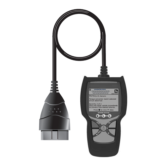
MD60b
CodeAdvisor
DIGITAL CODE READER
Operating Instructions
Safety Information
FEATURES AND BENEFITS
The easiest and best way to troubleshoot 1996 and newer OBD2 vehicles.
Links to all OBD2 protocols to decode "Check Engine" light problems.
Retrieves generic and manufacturer specific codes.
Displays Freeze Frame Data.
Advertisement
Table of Contents

Related Manuals for Matco Tools CodeAdvisor MD60b


Summary of Contents for Matco Tools CodeAdvisor MD60b
- Page 1 MD60b CodeAdvisor DIGITAL CODE READER Operating Instructions Safety Information FEATURES AND BENEFITS The easiest and best way to troubleshoot 1996 and newer OBD2 vehicles. Links to all OBD2 protocols to decode "Check Engine" light problems. Retrieves generic and manufacturer specific codes. Displays Freeze Frame Data.
-
Page 2: Table Of Contents
Table of Contents ABOUT THE SCAN TOOL SAFETY FIRST! ............... CONTROLS AND INDICATORS ..........DISPLAY FUNCTIONS ............INITIAL ADJUSTMENTS ............ONBOARD DIAGNOSTICS COMPUTER ENGINE CONTROLS ......... DIAGNOSTIC TROUBLE CODES (DTCs) ......OBD2 MONITORS ` ..............USING THE SCAN TOOL CODE RETRIEVAL PROCEDURE .......... ERASING DIAGNOSTIC TROUBLE CODES (DTCs) .... -
Page 3: About The Scan Tool
About the Scan Tool SAFETY FIRST SAFETY FIRST! This manual describes common test procedures used by experienced service technicians. Many test procedures require precautions to avoid accidents that can result in personal injury, and/or damage to your vehicle or test equipment. Always read your vehicle's service manual and follow its safety precautions before and during any test or service procedure. -
Page 4: Controls And Indicators
About the Scan Tool CONTROLS AND INDICATORS CONTROLS AND INDICATORS Figure 1. Controls and Indicators See Figure 1 for the locations of items 1 through 9, below. ERASE button - Erases Diagnostic Trouble Codes (DTCs) and "Freeze Frame" data from your vehicle's computer, and resets Monitor status. -
Page 5: Display Functions
About the Scan Tool DISPLAY FUNCTIONS MENU/ENTER button - Press and hold to display the Main Menu. When in Menu mode, press to confirm the selected option or value. When viewing the “Priority” code, press to view Freeze Frame data. 6. - Page 6 About the Scan Tool DISPLAY FUNCTIONS A flashing green/gray icon indicates the Monitor has not completed “This Driving Cycle” testing. A flashing red/gray icon indicates the Monitor has been disable for “This Driving Cycle.” Vehicle icon - When visible, indicates that the scan tool is being powered through the vehicle’s DLC connector.
-
Page 7: Initial Adjustments
About the Scan Tool INITIAL ADJUSTMENTS 2 - Repair immediately if drivability issues are present. Threat to essential system components if not repaired as soon as possible. 3 - Stop and repair vehicle immediately to prevent interrelated failures. Harmful and damaging to essential system components. Bluetooth icon –... -
Page 8: Onboard Diagnostics
Onboard Diagnostics COMPUTER ENGINE CONTROLS COMPUTER ENGINE CONTROLS The Introduction of Electronic Engine Controls Electronic Computer Control Systems make it possible for vehicle manufacturers to comply with the tougher emissions and fuel efficiency standards mandated by State and Federal Governments. As a result of increased air pollution (smog) in large cities, such as Los Angeles, the California Air Resources Board (CARB) and the Environmental Protection Agency (EPA) - Page 9 Onboard Diagnostics COMPUTER ENGINE CONTROLS The Basic Engine Computer Control System The Computer Control System consists of an on-board computer and several related control devices (sensors, switches, and actuators). The on-board computer is the heart of the Computer Control System. The computer contains several programs with preset reference values for air/fuel ratio, spark or ignition timing, injector pulse width, engine speed, etc.
- Page 10 Onboard Diagnostics COMPUTER ENGINE CONTROLS Vehicle operating conditions are constantly changing. The computer continuously makes adjustments or corrections (especially to the air/fuel mixture and spark timing) to keep all the engine systems operating within the preset reference values. On-Board Diagnostics - First Generation (OBD1) With the exception of some 1994 and 1995 vehicles, most vehicles from 1982 to 1995 are equipped with some type of first generation On-Board Diagnostics.
- Page 11 Onboard Diagnostics COMPUTER ENGINE CONTROLS Because OBD1 systems only detect failed components, the degraded components were not setting codes. Some emissions problems related to degraded components only occur when the vehicle is being driven under a load. The emission checks being conducted at the time were not performed under simulated driving conditions.
- Page 12 Onboard Diagnostics COMPUTER ENGINE CONTROLS Powertrain Control Module (PCM) - The PCM is the OBD2 accepted term for the vehicle’s “on-board computer.” In addition to controlling the engine management and emissions systems, also participates in controlling powertrain (transmission) operation. Most PCMs also have the ability to communicate with other computers on the vehicle (ABS, ride control, body, etc.).
-
Page 13: Diagnostic Trouble Codes (Dtcs)
Onboard Diagnostics DIAGNOSTIC TROUBLE CODES (DTCs) OBD2 Drive Cycle - An OBD2 Drive Cycle is an extended set of driving procedures that takes into consideration the various types of driving conditions encountered in real life. These conditions may include starting the vehicle when it is cold, driving the vehicle at a steady speed (cruising), accelerating, etc. - Page 14 Onboard Diagnostics DIAGNOSTIC TROUBLE CODES (DTCs) Manufacturer-Specific DTCs are codes that are controlled by the vehicle manufacturers. The Federal Government does not require vehicle manufacturers to go beyond the standardized generic DTCs in order to comply with the new OBD2 emissions standards.
- Page 15 Onboard Diagnostics DIAGNOSTIC TROUBLE CODES (DTCs) DTCs and MIL Status When the vehicle’s on-board computer detects a failure in an emissions-related component or system, the computer’s internal diagnostic program assigns a diagnostic trouble code (DTC) that points to the system (and subsystem) where the fault was found.
-
Page 16: Obd2 Monitors
Onboard Diagnostics OBD2 MONITORS If the conditions that caused the MIL to light are no longer present for the next three trips in a row, the computer automatically turns the MIL “Off” if no other emissions-related faults are present. However, the DTCs remain in the computer’s memory as a history code for 40 warm-up cycles (80 warm-up cycles for fuel and misfire faults). - Page 17 Onboard Diagnostics OBD2 MONITORS Non-Continuous Monitors The other twelve Monitors are “non-continuous” Monitors. “Non- continuous” Monitors perform and complete their testing once per trip. The “non-continuous” Monitors are: Oxygen Sensor Monitor Oxygen Sensor Heater Monitor Catalyst Monitor Heated Catalyst Monitor EGR System Monitor EVAP System Monitor Secondary Air System Monitor...
- Page 18 Onboard Diagnostics OBD2 MONITORS Fuel System Monitor - This Monitor uses a Fuel System Correction program, called Fuel Trim, inside the on-board computer. Fuel Trim is a set of positive and negative values that represent adding or subtracting fuel from the engine. This program is used to correct for a lean (too much air/not enough fuel) or rich (too much fuel/not enough air) air-fuel mixture.
- Page 19 Onboard Diagnostics OBD2 MONITORS of) the converter. If the catalytic converter loses its ability to store oxygen, the downstream sensor signal voltage becomes almost the same as the upstream sensor signal. In this case, the monitor fails the test. The Catalyst Monitor is supported by “spark ignition” vehicles only. The Catalyst Monitor is a “Two-Trip”...
- Page 20 Onboard Diagnostics OBD2 MONITORS via a purge solenoid. The computer energizes or de-energizes the purge solenoid (depending on solenoid design). The purge solenoid opens a valve to allow engine vacuum to draw the fuel vapors from the canister into the engine where the vapors are burned. The EVAP Monitor checks for proper fuel vapor flow to the engine, and pressurizes the system to test for leaks.
- Page 21 Onboard Diagnostics OBD2 MONITORS computer to enter into closed-loop operation. The oxygen sensor only functions when the computer is in closed-loop. A properly operating oxygen sensor reacts quickly to any change in oxygen content in the exhaust stream. A faulty oxygen sensor reacts slowly, or its voltage signal is weak or missing.
- Page 22 Onboard Diagnostics OBD2 MONITORS If the fault is sensed again on the second trip, the computer commands the MIL “On,” and saves the code in its long-term memory. NOx Aftertreatment Monitor - NOx aftertreatment is based on a catalytic converter support that has been coated with a special washcoat containing zeolites.
- Page 23 Onboard Diagnostics OBD2 MONITORS PM Filter Monitor - The particulate matter (PM) filter removes particulate matter from the exhaust stream by filtration. The filter has a honeycomb structure similar to a catalyst substrate, but with the channels blocked at alternate ends. This forces the exhaust gas to flow through the walls between the channels, filtering the particulate matter out.
- Page 24 Onboard Diagnostics OBD2 MONITORS Name of Monitor Comprehensive Continuous Component Monitor Misfire Monitor 3 - similar Continuous (Type 1 and 3) conditions Misfire Monitor 3 - similar Continuous (Type 2) conditions Fuel System Monitor 3 - similar Continuous 1 or 2 conditions Catalytic Converter Once per...
-
Page 25: Using The Scan Tool
Using the Scan Tool CODE RETRIEVAL PROCEDURE CODE RETRIEVAL PROCEDURE Retrieving and using Diagnostic Trouble Codes (DTCs) for troubleshooting vehicle operation is only one part of an overall diagnostic strategy. Never replace a part based only on the DTC definition. Each DTC has a set of testing procedures, instructions and flow charts that must be followed to confirm the location of the problem. - Page 26 Using the Scan Tool CODE RETRIEVAL PROCEDURE 6. The Scan Tool automatically starts a check of the vehicle’s computer to determine which type of communication protocol it is using. When the Scan Tool identifies the computer’s communication protocol, a communication link is established. A PROTOCOL is a set of rules and procedures for regulating data transmission between computers, and between testing equipment and computers.
- Page 27 Using the Scan Tool CODE RETRIEVAL PROCEDURE To select a new vehicle, highlight Select New Vehicle, then press MENU/ENTER The Select Year screen displays. Select the desired vehicle model year, then press MENU/ENTER continue, select Saved Vehicle to return to the Select Vehicle screen select...
- Page 28 Using the Scan Tool CODE RETRIEVAL PROCEDURE 11. In cases where “manufacturer specific” code (P1XXX, U1XXX, etc.) is displayed and the Scan Tool has not determined the vehicle make and model year (either by decoding the VIN or through manual selection), the Select Make Definition screen...
- Page 29 Using the Scan Tool CODE RETRIEVAL PROCEDURE Red LED - Indicates there is a problem with one or more of the vehicle's systems. The red LED is also used to show that DTC(s) are present. In this case, the Malfunction Indicator (Check Engine) lamp on the vehicle's instrument panel will light steady on.
-
Page 30: Erasing Diagnostic Trouble Codes (Dtcs)
Using the Scan Tool ERASING DIAGNOSTIC TROUBLE CODES (DTCs) ERASING DIAGNOSTIC TROUBLE CODES (DTCs) When the Scan Tool’s ERASE function is used to erase DTCs from the vehicle's on-board computer, "Freeze Frame" data and manufacturer-specific enhanced data are also erased. "Permanent" DTCs ARE NOT erased by the ERASE function. -
Page 31: About Repairsolutions 2
Using the Scan Tool ABOUT REPAIRSOLUTIONS 2® 6. If the erase was not successful, an advisory message shows indicating the erase request was sent to the vehicle’s computer. The Scan Tool automatically relinks to the vehicle’s computer after 3 seconds. ABOUT REPAIRSOLUTIONS 2®... -
Page 32: Connecting To Bluetooth / Wifi
Using the Scan Tool CONNECTING TO BLUETOOTH / WIFI 5. The RepairSolutions 2 app automatically displays a report based on the retrieved diagnostic data. If the Code Reader is not connected to WiFi or Bluetooth, vehicle data will not be saved. CONNECTING TO BLUETOOTH / WIFI Launch the RepairSolutions2 app an follow the prompts to establish Bluetooth and (optionally) WiFi connections, as follows:... -
Page 33: Live Data Mode
Live Data Mode VIEWING LIVE DATA The Scan Tool is a special tool that communicates with the vehicle's computer. The Scan Tool lets you view and/or "capture" (record) "real-time" Live Data. This information includes values (volts, rpm, temperature, speed etc.) and system status information (open loop, closed loop, fuel system sta- tus, etc.) generated by the various vehicle sensors, switches and actuators. - Page 34 Live Data Mode VIEWING LIVE DATA If Live Data is not supported by the vehicle under test, an advisory message displays. Press MENU/ENTER button to return to the Main Menu. Live Data is not available for your vehicle. Remember, what you are viewing is "real-time"...
-
Page 35: Additional Functions
Additional Functions VIEWING VEHICLE INFORMATION In addition to retrieving Diagnostic Trouble Codes (DTCs), you can use the scan tool to perform additional diagnostic tests, to view diagnostic and vehicle information stored in your vehicle's on-board computer, and to configure the scan tool for your particular needs. Additional tests and related functions are accessed through the Main Menu. - Page 36 Additional Functions VIEWING VEHICLE INFORMATION Retrieving Vehicle ID Information The Vehicle ID function is applicable to model year 2000 and newer OBD2-compliant vehicles. The Scan Tool can retrieve a list of information (provided by the vehicle manufacturer), unique to the vehicle under test, from the vehicle's on- board computer.
-
Page 37: Viewing Monitor Icon Descriptions
Additional Functions VIEWING MONITOR ICON DESCRIPTIONS - BATTERY/ALTERNATOR TEST Viewing In-use Performance Tracking (IPT) The Scan Tool can retrieve In-use Performance Tracking (IPT) statistics for monitors supported by the vehicle under test. Two values are returned for each monitor; the number of times that all conditions necessary for a specific monitor to detect a malfunction have been encountered (XXXCOND), and the number of times that the vehicle has been operated under the specific conditions for the monitor (XXXCOMP). - Page 38 Additional Functions BATTERY/ALTERNATOR TEST To access the Battery/Alternator Test menu: 1. Press MENU/ENTER The Main Menu displays. 2. Select Battery/Alternator Test, then press MENU/ENTER In cases where the Scan Tool has not determined the vehicle make and model year (either by decoding the VIN or through manual selection during code retrieval), the Select Vehicle screen displays.
- Page 39 Additional Functions BATTERY/ALTERNATOR TEST If the Scan Tool detects that a DTC related to the vehicle’s battery or charging system is present in the vehicle’s com- puter, a “Warning” message displays. Perform the neces- sary service procedures to correct the malfunction before performing battery/ alternator test.
- Page 40 Additional Functions BATTERY/ALTERNATOR TEST 6. Start the vehicle’s engine. Allow the engine to run for several seconds, then turn the engine off. If the Scan Tool did not detect “cranking status” for the vehicle’s engine, an advisory message shows. Select Next, then press MENU/ENTER to repeat the battery check, or, press MENU/ENTER...
-
Page 41: Viewing Led Definitions
Additional Functions LED DEFINITIONS - DISPLAY LANGUAGE - DISPLAY BRIGHTNESS Red = Excessive over charging or under charging If the alternator voltage is less than 9 V, the red, yellow and green SYSTEM STATUS LEDs will flash on and off. 6. -
Page 42: Enabling/Disabling The Audible Tone
Additional Functions AUDIBLE TONE - FOOTERS - HOTKEY LEGEND – UNIT OF MEASURE ENABLING/DISABLING THE AUDIBLE TONE 1. Select Audible Tone in the Main Menu, then press MENU/ENTER The Audible Tone screen displays. 2. Select On or Off as desired, then press MENU/ENTER to save your changes. -
Page 43: Viewing The Firmware Version
Additional Functions VIEWING FIRMWARE VERSION - SMOG CHECK / I/M PROGRAM LOCATION VIEWING THE FIRMWARE VERSION 1. Select Firmware Version in the Main Menu, then press MENU/ENTER Firmware Version screen displays. The screen shows the Scan Tool’s current firmware version, bootloader version and database version. -
Page 44: Viewing Monitor Icon Status Definitions
Additional Functions VIEWING MONITOR ICON STATUS DEFINITIONS If the information shown is not correct for the vehicle under test, or if you wish to reselect the vehicle, select No, then press MENU/ENTER to return to the Select Vehicle screen. 2. - Page 45 Notes...
- Page 46 Notes...
-
Page 47: Warranty And Servicing
Warranty and Servicing LIMITED TWO YEAR WARRANTY The Manufacturer warrants to the original purchaser that this unit is free of defects in materials and workmanship under normal use and maintenance for a period of two (2) years from the date of original purchase. - Page 48 17352 Von Karman Avenue Irvine, CA 92614 Printed in Taiwan Instruction MRP #93-XXXX Copyright © 2021 IEC. All Rights Reserved.
Need help?
Do you have a question about the CodeAdvisor MD60b and is the answer not in the manual?
Questions and answers