Sony EVI-HD1 Technical Manual
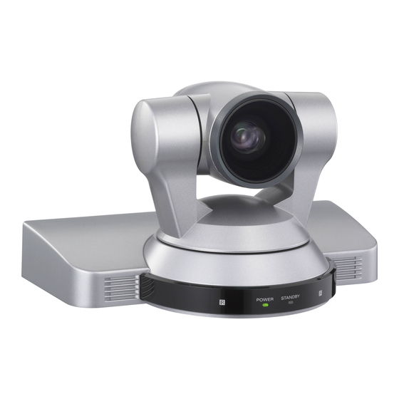
Hd color video camera
Hide thumbs
Also See for EVI-HD1:
- Operating instructions manual (84 pages) ,
- Technical manual (4 pages) ,
- Specifications (2 pages)

Related Manuals for Sony EVI-HD1


Summary of Contents for Sony EVI-HD1
- Page 1 A-CKC-100-11(1) HD Color Video Camera Technical Manual EVI-HD1 2006 Sony Corporation...
-
Page 2: Table Of Contents
Connection ... 4 Locations of Controls ... 5 Basic Functions ... 8 Initial Settings and Position Preset ... 13 Mode Condition ... 14 Command List ... 19 VISCA RS-232C Commands ... 19 EVI-HD1 Commands ... 26 Specifications ... 38 Precautions ... 40... -
Page 3: Features
• The CMOS video camera provides 2,000,000 effective picture elements (pixels) that can shoot high-definition images to offer superior picture quality. • By adopting the DD motor mechanism, in addition to high-speed pan/tilt action, improvement of the noise reduction mechanism lets you use the camera for a variety of purposes. -
Page 4: Connection
to SD OUT VIDEO to DC IN 12V 1) When the camera is connected to a computer with a VISCA cable (cross type, RS-232C), you can operate the camera with the computer. To obtain a cable, consult the dealer where you bought your camera. 2) To VISCA IN of other EVI-HD1s (when connecting to more than one camera) 3) The HD OUT COMPONENT output is not compatible with a computer display that does not support HDTV formats. -
Page 5: Main Unit
Locations of Controls Main Unit Front Rear 1 Lens 2 Remote sensors 3 POWER lamp 4 STANDBY lamp For detailed information on LED status of the POWER lamp and STANDBY lamp, see “LED Status” on page 37. Bottom 5 DC IN 12V connector 6 SYSTEM SELECT switch This switch allows you to select the video format of the signal to be output from the HD OUT COMPONENT, HD... - Page 6 the power of the camera by connecting it to an AC outlet using the supplied AC power adaptor and AC power cord, or by using the VISCA command. When you set this switch in the standby mode, press the POWER switch of the remote commander.
-
Page 7: Remote Commander
2 Switch 2 (Communication baud rate selector) Set to ON for 38400 bps, or OFF for 9600 bps. Note Set the communication baud rate before turning on the power. If you set the communication baud rate after turning on the power, the setting is ignored. 3 Switch 3 (Not used) Be sure to set this switch to OFF. -
Page 8: Basic Functions
Zoom The camera employs an 10× optical zoom lens combined with a digital zoom function allowing you to zoom up to 40×. Lens specifications: Optical 10×, f = 3.4 to 33.9 mm (F1.8 to F2.1) The horizontal angle of view is approximately 70 degrees (wide end) to 8 degrees (tele end). -
Page 9: Automatic Exposure Mode
White Balance White Balance has the following modes, all of which can be set using VISCA Commands. • Auto White Balance This mode computes the white balance value output using color information from the entire screen. It outputs the proper value using the color temperature radiating from a black subject based on a range of values from 3000 to 7500K. - Page 10 AE – Iris Priority The iris can be set freely by the user to 18 steps between F1.8 and Close. The gain and shutter speed are set automatically according to the brightness of the subject. parameter IRIS (F1.8) F No. parameter F1.8 F2.0...
-
Page 11: Back Light Compensation
Exposure Compensation Exposure compensation is a function which offsets the internal reference brightness level used in the AE mode by steps of 1.5 dB. EXPOSURE Comp Step Value +10.5dB +9dB +7.5dB +6dB +4.5dB +3dB +1.5dB –1.5dB –3dB –4.5dB –6dB –7.5dB –9dB –10.5dB Aperture Control... - Page 12 Basic Functions Memory (Position Preset) Using the position preset function, 6 sets of camera shooting conditions can be stored and recalled. This function allows you to achieve the desired status instantly even without adjusting the following items each time: • Pan-Tilt position •...
-
Page 13: Initial Settings And Position Preset
Initial Settings and Position Preset The initial values are those set at the factory. Settings for items in Position presets 1 to 6 that will be retained even when the power to the camera is turned off are indicated by a “O,” those that will be lost are indicated by an “X.”... -
Page 14: Mode Condition
Basic Functions... - Page 15 Basic Functions...
- Page 16 Basic Functions...
- Page 17 Basic Functions...
- Page 18 Basic Functions...
-
Page 19: Visca Rs-232C Commands
1) VISCA is a protocol which controls consumer camcorders developed by Sony. “VISCA” is a trademark of Sony Corporation. Command List The VISCA devices each have a VISCA IN and VISCA OUT connector. -
Page 20: Timing Chart
(Fig. 2). The first byte of the packet is called the header and comprises the sender’s and receiver’s addresses. For example, the header of the packet sent to the EVI-HD1 assigned address 1 from the controller (address 0) is hexadecimal 81H. The packet sent to the Header Byte 1 Sender’s... - Page 21 No socket (to be cancelled) X0 6Y 41 FF Command not executable X = 9 to F: EVI-HD1 address + 8, Y = socket number Socket number When command messages are sent to the EVI-HD1, it is normal to send the next command message after waiting for the completion message or error message to return.
-
Page 22: Visca Device Setting Command
IF_Clear (broadcast) 88 01 00 01 FF X = 1 to 7: EVI-HD1 address (For inquiry packet) X = 9 to F: EVI-HD1 address +8 (For reply packet) VISCA interface and inquiry ● CAM_VersionInq Returns information on the VISCA interface. -
Page 23: Pin Assignment
IR OUT (R)* IR OUT (L)* * You can change ON/OFF of IR OUT of pins 7 and 8 using the BOTTOM switch (see page 6). • EVI-HD1 Windows D-sub 9 pin • EVI-HD1 EVI Camera or Mini DIN 8 pin serial •... -
Page 24: Visca Command/Ack Protocol
VISCA Command/ACK Protocol Command Command Message General Command 81 01 04 38 02 FF (Example) 81 01 04 38 FF (Example) 81 01 04 38 02 FF (Example) 81 01 04 08 02 FF (Example) Inquiry Command 81 09 04 38 FF (Example) 81 09 05 38 FF (Example) -
Page 25: Error Messages
VISCA Camera-Issued Messages ACK/Completion Messages Command Messages z0 4y FF (y:Socket No.) Completion z0 5y FF (y:Socket No.) z = Device address + 8 Error Messages Command Messages Syntax Error z0 60 02 FF Command Buffer Full z0 60 03 FF Command Canceled z0 6y 04 FF (y:Socket No.) -
Page 26: Evi-Hd1 Commands
EVI-HD1 Commands EVI-HD1 Command List (1/3) Command Set Command AddressSet Broadcast IF_Clear Broadcast CommandCancel CAM_Power CAM_Zoom Stop Tele(Standard) Wide(Standard) Tele(Variable) Wide(Variable) Direct CAM_DZoom D-Zoom Limit CAM_Focus Stop Far(Standard) Near(Standard) Far(Variable) Near(Variable) Direct Auto Focus Manual Focus Auto/Manual One Push Trigger... - Page 27 EVI-HD1 Command List (2/3) Command Set Command CAM_AE Full Auto Manual Shutter Priority Iris Priority Bright CAM SpotLight CAM_SlowShutter AutoSlowShutterLimit CAM_Shutter Reset Down Direct CAM_Iris Reset Down Direct CAM_Gain Reset Down Direct CAM_Bright Reset Down Direct CAM_ExpComp Reset Down Direct...
- Page 28 EVI-HD1 Command List (3/3) Command Set Command CAM_IDWrite IR_Receive On/Off IR_ReceiveReturn D-SUB 15Pin SYNC 3-STATE Information Display Pan-tiltDrive Down Left Right UpLeft UpRight DownLeft DownRight Stop AbsolutePosition RelativePosition Home Reset Pan-tiltLimitSet LimitSet LimitClear 1) After an ACK to a One Push White Balance Trigger is sent until the operation is completed, “Not Executable” is sent as a reply when any other commands are received.
- Page 29 EVI-HD1 Inquiry Command List (1/2) Inquiry Command Command Packet CAM_PowerInq 8x 09 04 00 FF CAM_ZoomPosInq 8x 09 04 47 FF CAM_DZoomLimitInq 8x 09 04 26 FF CAM_FocusModeInq 8x 09 04 38 FF CAM_FocusPosInq 8x 09 04 48 FF CAM_FocusNearLimitInq...
- Page 30 EVI-HD1 Inquiry Command List (2/2) Inquiry Command Command Packet CAM_VersionInq 8x 09 00 02 FF D-SUB 15Pin SYNC 8x 09 7E 01 1A FF Information Display 8x 09 7E 01 18 FF VideoSystemInq 8x 09 06 23 FF IR_Receive 8x 09 06 08 FF...
- Page 31 EVI-HD1 Block Inquiry Command List Lens control system inquiry commands ... Command Packet 8x 09 7E 7E 00 FF Byte Bit Comments Destination Address Source Address 0 Completion Message (50h) Zoom Position (HH) Zoom Position (HL) Zoom Position (LH) Zoom Position (LL)
- Page 32 Camera control system inquiry commands .. Command Packet 8x 09 7E 7E 01 FF Byte Bit Comments Destination Address Source Address 0 Completion Message (50h) WB R_Gain (H) WB R_Gain (L) WB B_Gain (H) WB B_Gain (L) Byte Bit Comments OnePush RES 0: Inquiring 1: OK 2: NG WB Mode...
- Page 33 Other inquiry commands ... Command Packet 8x 09 7E 7E 02 FF Byte Bit Comments Destination Address Source Address 0 Completion Message (50h) Power 1: On 0: Off Picture Effect Mode Byte Bit Comments Camera ID (HH) Camera ID (HL) Camera ID (LH) Camera ID (LL) Command List...
- Page 34 Enlargement Function Query Command ... Command Packet 8x 09 7E 7E 03 FF Byte Bit Comments Destination Address Source Address 0 Completion Message (50h) Byte Bit Comments Command List Byte Bit Comments Auto Slow Shutter Limit D-Zoom Limit 1 Terminator (FFh)
-
Page 35: Visca Command Setting Values
VISCA Command Setting Values Exposure Control (1/2) 59.94/29.97/NTSC Shutter Speed 10000 6000 4000 3000 2000 1500 1000 Iris F1.8 F2.0 F2.4 F2.8 F3.4 F4.0 F4.8 F5.6 F6.8 F8.0 F9.6 CLOSE Gain 50/25/PAL 10000 6000 3500 2500 1750 1250 1000 Command List 18 dB 15 dB 12 dB... - Page 36 Exposure Control (2/2) IRIS Bright F1.8 F1.8 F1.8 F1.8 F1.8 F1.8 F1.8 F2.0 F2.4 F2.8 F3.4 F4.0 F4.8 F5.6 F6.8 F8.0 F9.6 CLOSE Step Exposure Comp. –1 –2 –3 –4 –5 –6 –7 Zoom Ratio and Zoom Position (for reference) GAIN 18 dB Zoom Ratio...
-
Page 37: Led Status
Pan/Tilt Status Code List - - - - - - - - 0 - - - - - - 1 A Pan movement all the way to the left - - - - - - - - 0 - - - - - 1 - A Pan movement all the way to the right - - - - - - - - 0 - - - - 1 - - A Tilt movement all the way up - - - -... -
Page 38: Specifications
System Video signal 1080i/59.94, 1080i/50, 1080p/29.97, 1080p/25, 720p/59.94,720p/50, 720p/29.97, 720p/25, NTSC (LB), NTSC (CR), NTSC (SQ), PAL (LB), PAL(CR), PAL (SQ) (switched with the SYSTEM SELECT switch) Synchronization Internal synchronization Image device 1/3 type (6 mm), CMOS Effective picture elements: Approx. 2,000,000 pixels 10 ×... - Page 39 Specifications Dimensions Front Side Bottom Unit: mm (inches)
-
Page 40: Operation
Do not apply excessive voltage. (Use only the specified voltage.) Otherwise, you may get an electric shock or a fire may occur. In case of abnormal operation, contact your authorized Sony dealer or the store where you purchased the product.
Need help?
Do you have a question about the EVI-HD1 and is the answer not in the manual?
Questions and answers
DO you need WI-FI to operate this camera ? (Sony EV1-HD1)
No, the Sony EVI-HD1 camera does not require Wi-Fi to operate. It uses wired connections such as HD-SDI for video output and RS-232C VISCA for control.
This answer is automatically generated