Table of Contents
Advertisement
Quick Links
TMG-TMO70
PRODUCT MANUAL
v2023.03.02
70" 3-POINT HITCH
ORCHARD FINISHING MOWER
Please read and understand the product manual completely before assembly
Check against the parts list to make sure all parts are received
Wear proper safety goggles or other protective gears while in assembly
Do not return the product to dealer. They are not equipped to handle your requests.
Missing parts or questions on assembly?
Please call: 1-877-761-2819 or email: cs@tmgindustrial.com
Advertisement
Table of Contents

Related Manuals for TMG TMG-TMO70


Summary of Contents for TMG TMG-TMO70
- Page 1 TMG-TMO70 PRODUCT MANUAL v2023.03.02 70” 3-POINT HITCH ORCHARD FINISHING MOWER Please read and understand the product manual completely before assembly Check against the parts list to make sure all parts are received Wear proper safety goggles or other protective gears while in assembly Do not return the product to dealer.
-
Page 2: Table Of Contents
TABLE OF CONTENTS IMPORTANT SAFETY INFORMATION....................3 GENERAL SAFETY GUIDELINES......................4 PRODUCTS SPECIFICATIONS.......................7 PARTS DESCRIPTION AND FUNCTION..................8 SAFETY DECAL LOCATIONS......................9 UNPACKING & ASSEMBLY......................11 CONNECTING TRACTOR.......................18 PRIOR TO OPERATION........................20 MAINTENANCE..........................24 STORAGE............................28 TROUBLESHOOTING........................28 EXPLODED VIEW & PARTS LIST....................30... -
Page 3: Important Safety Information
IMPORTANT SAFETY INFORMATION Before operating the MOWER read the following safety instructions. Failure to comply with these warnings may result in serious injury or death. Safety Instructions Good safety practices not only protect you but also the people around you. Please ensure that everyone using his equipment is familiar with the recommended operating and maintenance procedures, has read and understood the Operators Manual and follows all the safety precautions. -
Page 4: General Safety Guidelines
GENERAL SAFETY GUIDELINES • Have a first-aid kit available for use and know how to use it. • Have a fire extinguisher available, stored in a highly visible location and know how to use it. • Wear appropriate protective gear. This list may include but is not limited to: - hard hat - protective shoes with slip resistant soles and steel caps - protective glasses or goggles... - Page 5 Employer/Controller Responsibilities OH&S legislation places obligations on the employer, or the controller of the Mower, to identify the hazards and control the risks associated with the use of the Mower in their workplace and to do so in accordance with the manufacturer's instructions. When purchasing a Mower: 1.
- Page 6 Start-up Safety Do not let inexperienced operators or children use this equipment. Place all tractor and machine controls in neutral before starting. Operate only with Roll Over Protective System(ROPS) and seat belt equipped tractors. Do not operate inside a building unless there is adequate ventilation. Ensure all shields are in place and in good condition before operating.
-
Page 7: Products Specifications
Remove the smallest portion of the split backing paper and align over the specified area. Carefully press in place. Slowly peel back the remaining paper and smooth the remaining portion in place. Small air pockets can be pierced with a pin and smoothed out. PRODUCTS SPECIFICATIONS Model TMG-TMO70 Working width 70” Max. working width 85” Cutting height 1”-3”... -
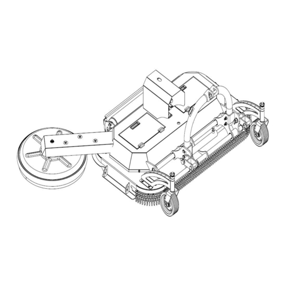
Page 8: Parts Description And Function
PARTS DESCRIPTION AND FUNCTION 1. PTO shaft —— Transfer the tractor power output to the gearbox. 2. Three point suspension assembly—— linkage Connect tractor and Mower. 3. Hydraulic lateral moving components—— Push the mower left and right with the hydraulic cylinder to control the mowing range. -
Page 9: Safety Decal Locations
SAFETY DECAL LOCATIONS The safety decals and their positions are shown on the illustration below. Good safety requires that you familiarize yourself with the various safety decals, the type of warning and the area or specific function related to that area that requires your SAFETY AWARENESS. - Page 10 0011 0011...
-
Page 11: Unpacking & Assembly
UNPACKING & ASSEMBLY & ASSEMBLY 1. After unpacking, check the following components The parts marked with numbers in the figure are the parts that need to be assembled. *. All numbers are not part numbers in the drawings. For correct part numbers, see explosive diagram. - Page 12 DESCRIPTION DESCRIPTION Host Full thread hexagon bolt M10x20 Roller assembly Spring washer Ø10 Full thread hexagon bolt M12x35 Plain washer Ø10 Plain washer Ø12 Suspension components Hex lock nut M12 Hexagon bolt M12x120 Floating plate weldments Floating mowing assembly Hexagon bolt M22x120 Belt cover Plain washer Ø22 Fixed gasket...
- Page 13 2. Install the roller assembly D5-D6-D7 Installation steps: Lift the HOST (A1) with a forklift, place the ROLLER ASSEMBLY (B46) at the position shown in the figure, align it with the mounting hole on the host, and fix it with BOLTS(D7), PLAIN WASHER(D5) and NUTS (D6). NOTE: Place a flat washer on the bolt side and nut side respectively.
- Page 14 3. Install the floating plate weldments Installation steps: Place the FLOATING PLATE WELDMENTS (B33) in the position shown in the figure above, align it with the mounting holes on the host, and fasten it with BOLTS (B34) and LOCK NUTS(B16) , PLAIN WASHER(B15), and then insert the LOWER HANGING PIN (B35) and LOCKING PIN(B30).
- Page 15 4. Install the wheel fork assembly J10-J11-J12 Installation steps: Place the WHEEL FORK ASSEMBLY (B45) in the position shown in the figure above, align it with the mounting holes on the host, Install the wheel fork assembly and host with BOLTS (J12), SPRING WASHERS (J11) and PALIN WASHERS (J10), and tighten it. (left and right symmetrical installation) Importance: All bolts are locked in place without shaking.
- Page 16 5. Install suspension components A15-A16-A17 Installation steps: Place the SUSPENSION COMPONENTS (A14) at the position shown in the figure above, and connect the suspension assembly and guide rail base with NUTS (A16), PLAIN WASHERS (A15) and BOLTS (A17). Importance: All bolts are locked in place without shaking. NOTE: M12 Torque is 87 N·m WARNING: Once the assembly bolts are not fastened in place, there will be abnormal noises when the machine is working.
- Page 17 6. Install the Floating cutter assembly A20-A21-A22-A23...
- Page 18 Installation steps: 1. First remove the BELT COVER (A10) from the FLOATING CUTTER ASSEMBLY (A6). 2. Then place the floating cutter assembly in the position shown above, put the GATES BELT (A13) over the pulley, install the BLOTS (A9), SPRING WASHER (A8), PLAIN WASHER (A7), do not lock first, 3.
-
Page 19: Connecting Tractor
In the process of connection, when the tractor is the moving, if there is people between the tractor and working machine, it may cause injury accident. Be sure no people stand between the tractor and working machine during the tractor moving. LOWER LIFTING PIN TYPES TMG-TST48 CAT1 &CAT2 2. Connection and adjustment... - Page 20 3.PTO Installation In some cases it will be necessary to shorten the PTO assembly to match your particular tractor. The following procedure should be used: 1. Check that the driveline is the correct length. The minimum coupling length (overlap) must be no less than 150mm (6 inches) in each work position.The driveline travel must still be about 25mm (1 inch) in the maximum coupling (overlap) position.
-
Page 21: Prior To Operation
PRIOR TO OPERATION BEFORE PUTTING Mower INTO SERVICE IMPORTANT INSTRUCTIONS PRIOR TO OPERATING MUST BE FOLLOWED. MOWER SHIPPED WITHOUT OIL IN GEAR BOXSAND WITHOUT GREASE IN GREASE FITTINGS. UNIT MUST BE SERVICED BEFORE USING. Fill Gearbox using Multipurpose Gear Oil (SAE90). For all Grease Fittings use a high-temp/multipurpose grease. STEP1 Place Mower so that the deck is secure and level. - Page 22 Preparation Never operate the tractor and Mower until you have read and completely understand this manual, the Tractor Operator's Manual and each of the messages found on the safety decals on the tractor and Mower. Personal protection equipment including hard hat, safety glasses, safety shoes, hearing protection and gloves are recommended during assembly, installation, operation, adjustment, maintenance, repairing, removal, or moving the implement.
- Page 23 Disengage Power Take Off (PTO) and place tractor transmission in neutral before attempting to start engine. Many varied objects, such as wire, cable, rope or chains can become entangled in the working parts of the Mower. These objects could then swing outside the housing at a greater velocity than the blades. Such an occurrence is extremely hazardous. Inspect the cutting area for such objects before slashing.
-
Page 24: Maintenance
MAINTENANCE OPERATING INSTRUCTIONS The Cutting Height Adjustment The cutting height can be adjusted by the roller assembly and tail wheel assembly. When adjusting, first lift the mower by hanging, then loosen the fastening bolts of the roller assembly, and then tighten the bolts after adjusting to the appropriate height; Adjust the tail wheel after completing the adjustment of the roller. - Page 25 Maintenance Safety Good maintenance is your responsibility. • Follow good shop practices • Keep service area clean and dry. • Be sure electrical outlets and tools areproperly grounded. • Use adequate light for the job at hand. Make sure there is ample ventilation. Never operate tractor engine in a closed building. The exhaust fumes may cause asphyxiation.
- Page 26 AFTER EVERY EIGHT HOURS OF OPERATION 1. Grease PTO shaft as per instructions listed on bottom of next page. 2. Check Cutter Beam for any signs of damage and check Retaining Nut to gearbox is tight and split pin is still in place. 3.
- Page 27 PTO Shaft Maintenance The PTO shaft is designed to telescope to allow for dimensional changes as the machine goes through its operating range. A tubular guard encloses the driving components and is designed to remain stationary on a turning shaft when required. The shaft should telescope easily and the guard turn freely on the shaft at all times.
-
Page 28: Storage
STORAGE After the season’s use, the machine should be thoroughly inspected and prepared for storage. Repair or replace any worn or damaged components to prevent any unnecessary down time at the start of next season. To insure a long, trouble free life, follow the procedure outlined below: 1. - Page 29 PROBLEM PROBABLE CAUSE SOLUTION 1. Bolts not tightened --- Tighten bolts 2. Bolt hole elongated or oversized --- Replace blade carrier Blade bolts come loose 3. Blade bolt threads are worn or damaged --- Replace blade bolt, washer, nylock nut and hardened bush 1.
-
Page 30: Exploded View & Parts List
EXPLODED VIEW & PARTS LIST 1. Main-frame assembly PARTS LIST DESCRIPTION PART NO. DESCRIPTION PART NO. Explosion diagram of aircraft hood Gates belt Cover assembly Hitch weldment Plain washer Ø8 Plain washer Ø12 Spring washer Ø8 Locknut M12 Hexagon socket head cap screws Hexagon head bolts M12x120 M8x20 Floating cutter assembly... - Page 31 2. Explosion Diagram of Aircraft Hood B37 B36...
- Page 32 PARTS LIST DESCRIPTION PART NO. DESCRIPTION PART NO. Guide rail Combined sealing gaskets 13.7x20.6x2 Left guide seat weldment Hollow bolt G1/4 Right guide seat weldment Safety pin 12 Galvanized chain 6x28x20 Chain pin Hydraulic cylinder 40x275 Guide ring 36x42x15 Hood weldment Floating plate weldment Pulley Hexagon head bolts M22x120...
- Page 33 3. Cover assembly PARTS LIST DESCRIPTION PART NO. DESCRIPTION PART NO. Cover base weldment Zinc alloy die casting hinge 54x40xM6 PTO cover Pull handle 102x34 Gate cover Plain washer Ø6 Plain washer Ø8 Locknut M6 Spring washer Ø8 Magnet 30x15x5 Hexagon socket head cap screws M8x20...
- Page 34 4. Roller assembly PARTS LIST DESCRIPTION PART NO. DESCRIPTION PART NO. Roller weldment Self-aligning ball bearing 1305 Roller connecting plate A Shaft seal 40x62x8 Roller connecting plate B HSCS-countersunk M8 Bearing seat Retaining rings for bore Plain washer Ø12 Scraper Locknut M12 Plain washer Ø10 Full-thread hexagon bolts M12x35...
- Page 35 5. Cutter assembly PARTS LIST DESCRIPTION PART NO. DESCRIPTION PART NO. Blade Blade spacer Cutter weldment Plain washer Ø10 Fixed washer Spring washer Ø10 Full-thread hexagon bolts M10x50 Full-thread hexagon bolts M10x20 Locknut M10...
- Page 36 6. Bearing assembly PARTS LIST DESCRIPTION PART NO. DESCRIPTION PART NO. Deep groove ball bearing 6205 Square and rectangular keys 8x7x20 Axle Locknut M12 Bearing weldment Full-thread hexagon bolts M12x40 Plain washer Ø12 Spacer Pulley spacer Grease nipple G1/8...
- Page 37 7. Joint bearing assembly PARTS LIST DESCRIPTION PART NO. DESCRIPTION PART NO. Deep groove ball bearing 6205 Plain washer Ø12 Axle Locknut M12 Joint bearing seat weldment HSCS-countersunk M12x40 Pulley spacer Spacer Square and rectangular keys 8x7x20 Grease nipple G1/8...
- Page 38 8. Gearbox assembly PARTS LIST DESCRIPTION PART NO. DESCRIPTION PART NO. Mounting seat Locknut M14 Pulley HSCS-countersunk M14x45 Gear box Square and rectangular keys10x8x40 Large plain washer Ø12 Plain washer Ø24 Spring washer Ø12 Hexagon slotted and castle nuts M24 Full-thread hexagon bolts M12x40 Split pin 5x40 Plain washer Ø14...
- Page 39 9. Wheel fork assembly PARTS LIST DESCRIPTION PART NO. DESCRIPTION PART NO. Swivel fork support weldment Plain washer Ø12 Fork welded joint Hexagon head bolts M12x120 Plain washer Ø27 Locknut M12 Adjustment spacer Plain washer Ø10 Safety pin Ø12 Spring washer Ø10 Vehicle wheel 8X3-6005 Full-thread hexagon bolts M10x20...
- Page 40 10. Floating cutter assembly PARTS LIST DESCRIPTION PART NO. DESCRIPTION PART NO. Pulley Plain washer Ø10 Arm board weldment Spring washer Ø10 Deep groove ball bearing 61812 Full-thread hexagon bolts M10x20 Deep groove ball bearing 6205 Plain washer Ø20 Blade Round lock nut M20 Floating bearing seat Spacer...
- Page 41 11. Sliding Rod Assembly PARTS LIST DESCRIPTION PART NO. DESCRIPTION PART NO. Swivel fork support weldment Plain washer Ø12 Fork welded joint Hexagon head bolts M12x120 Plain washer Ø27 Locknut M12 Adjustment spacer Plain washer Ø10 Safety pin Ø12 Spring washer Ø10 Vehicle wheel 8X3-6005 Full-thread hexagon bolts M10x20...
- Page 42 12. Arm board assembly PARTS LIST DESCRIPTION PART NO. DESCRIPTION PART NO. Arm bearing seat weldment Insert bearing 6201 Deep groove ball bearing 61812 Spring-type straight pin 12x30 Plain washer Ø12 Spring-type straight pin M8x16 Bearing seat...
Need help?
Do you have a question about the TMG-TMO70 and is the answer not in the manual?
Questions and answers